Automatic welding equipment for parallel flow tube condenser connection tubes

A technology of automatic welding and parallel flow tubes, which is applied in welding equipment, auxiliary welding equipment, welding/cutting auxiliary equipment, etc., can solve the problems of long time consumption, high production cost, and easy leakage of welding, so as to improve production efficiency and ensure Applicable and maintain the effect of beauty

Inactive Publication Date: 2015-05-20
CHINA JILIANG UNIV
View PDF6 Cites 14 Cited by
  • Summary
  • Abstract
  • Description
  • Claims
  • Application Information

AI Technical Summary

Problems solved by technology

Traditional pipe welding is usually artificial flame welding, because the structure of the condenser itself is complex, the device for fixing it and the pipe is relatively complicated, the clamping and disassembly process takes a long time, and the symmetry and overall parallelism between the pipes after welding cannot be guaranteed; in addition Aluminum products have a low melting point, which is easy to miss welding and weld through the workpiece, which requires high technical requirements for welding personnel
At present, the production cost of the entire condenser manufacturing industry is high, and the efficiency is low, which restricts the automation transformation of the entire condenser industry

Method used


Image

  • Automatic welding equipment for parallel flow tube condenser connection tubes
  • Automatic welding equipment for parallel flow tube condenser connection tubes

Examples


Embodiment Construction

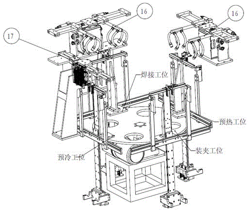
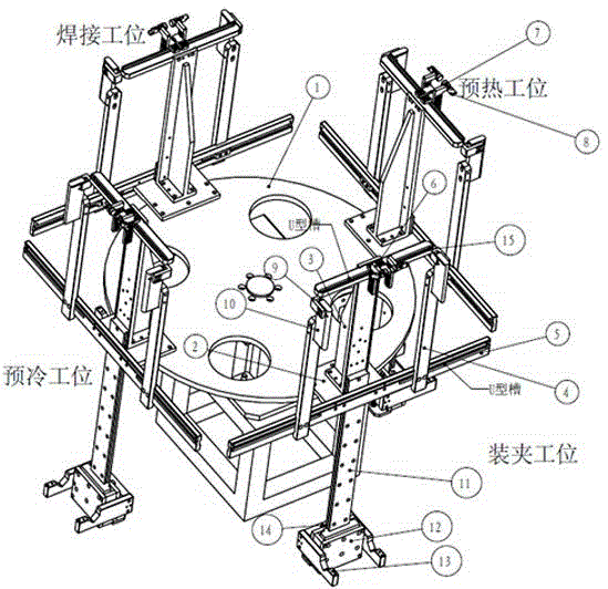
[0012] The present invention will be further described below in conjunction with accompanying drawing.

[0013] Such as figure 1 , 2 As shown, the automatic welding equipment based on the parallel flow tube condenser of the present invention includes a welding gun 16, a blowing cold pipe 17, a rotating platform 1, a condenser clamping device and a connecting pipe clamping device; the rotating platform 1 is fixed On the gear box, the entire disc is divided into four stations by an indexing device, which are clamping station, preheating station, welding station and precooling station, and each station is fixed with a sunken groove. The holes are used to fix the first connection plate 2 with screws, and the extension bracket 3 is fixed on the first connection plate 2, and the extension bracket 3 is used to connect and install the connecting pipe clamping device and the condenser clamping device.

[0014] The condenser clamping device includes a mobile bracket 4, a first sliding...


PUM


Abstract

The invention discloses automatic welding equipment for parallel flow tube condenser connection tubes. The automatic welding equipment for the parallel flow tube condenser connection tubes comprises welding guns (16), blast-cold tubes (17), a rotating platform (1), condenser clamping devices and connection tube clamping devices; the rotating platform is fixed on a speed-changing gear box, a whole disc is divided into four working positions, namely, a clamping working position, a preheating working position, a welding working position and a precooling working position, through dividing devices, sediment tank fixing holes are formed in each working position, connecting plates (2) are fixed through screws, extension supports (3) are fixed on the corresponding connecting plates (2), and the extension supports (3) are used for connecting and arranging the connection tube clamping devices and the condenser clamping devices. According to the automatic welding equipment for the parallel flow tube condenser connection tubes, multiple working position rotating disc welding is achieved, and the production efficiency is greatly improved; the position of the connection tube can be positioned accurately, and the beautiful welding outline is guaranteed; the clamping is guided through machinery, and the clamping efficiency is guaranteed; the condenser clamping devices and the connection tube clamping devices are all movable mechanical combined components, and the applicability of products is guaranteed.

Description

technical field [0001] The invention relates to the field of welding in the machinery manufacturing industry, in particular to an automatic welding device for connecting pipes of parallel flow tube condensers. Background technique [0002] Condenser tube welding is a key process in the condenser manufacturing industry. The connecting pipes vary in shape and size due to different uses. The connecting pipes of parallel flow tube condensers are usually in the shape of an "L", and the material is half aluminum and half copper. The aluminum part is welded to the condenser, and the copper part is the refrigerant charging channel. . Traditional pipe welding is usually artificial flame welding, because the structure of the condenser itself is complex, the device for fixing it and the pipe is relatively complicated, the clamping and disassembly process takes a long time, and the symmetry and overall parallelism between the pipes after welding cannot be guaranteed; in addition Alumi...

Claims


Application Information

Patent Timeline
IPC IPC(8): B23K37/00B23K37/04
CPCB23K37/00B23K37/003B23K37/02B23K37/0435B23K2101/14
Inventor 蒋庆张旺余海庆余清
Owner CHINA JILIANG UNIV
Why Eureka
Try Eureka