
Distributing mechanism for clamp assembly device

An assembly equipment and cloth technology, which is applied in the field of cloth mechanism for clip body assembly equipment, can solve the problems of low assembly efficiency and high labor intensity, and achieve the effect of accurate cloth and automatic assembly.

Active Publication Date: 2015-05-20
苏州伊那思纺织有限公司
View PDF6 Cites 0 Cited by
  • Summary
  • Abstract
  • Description
  • Claims
  • Application Information

AI Technical Summary

Problems solved by technology

At present, the assembly of fixtures is mainly carried out manually. One is that the assembly efficiency is low, and the other is that manual assembly is labor-intensive. Especially for some large-sized clips, the operating force for deforming and assembling the handle is relatively large.

Method used


Image

  • Distributing mechanism for clamp assembly device
  • Distributing mechanism for clamp assembly device
  • Distributing mechanism for clamp assembly device

Examples


Embodiment Construction

[0011] In order to make the objects and advantages of the present invention clearer, the present invention will be specifically described below in conjunction with examples. It should be understood that the following words are only used to describe one or several specific implementation modes of the present invention, and do not strictly limit the protection scope of the specific claims of the present invention.

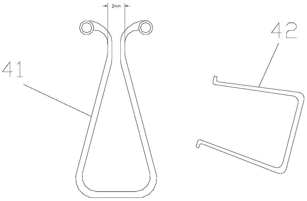
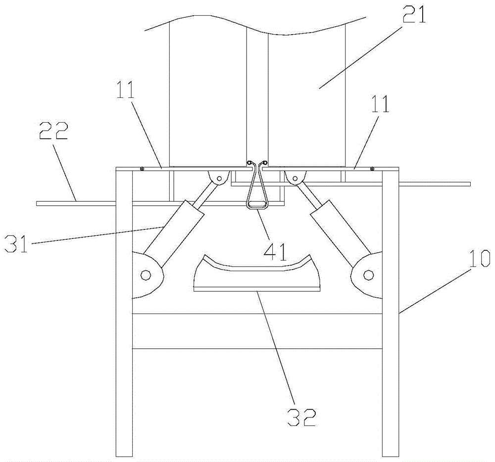
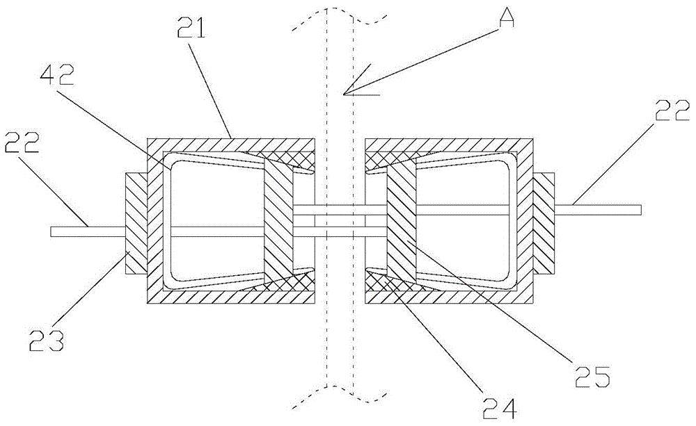
[0012] The technical scheme that the present invention takes is as figure 2 As shown, a distributing mechanism for clip body assembly equipment includes an assembly table for assembling clips. The table top of the assembly table is composed of two left and right boards 11. The size of the gap A between the two boards 11 is the same as the end surface of the clip body 41 The smallest width dimension of the (i.e. figure 1 The size shown in Dmin in the middle) coincides, the clip body 41 is fixed at the gap A between the two table boards 11 and the installation hole o...


PUM


Abstract

The invention discloses a distributing mechanism for a clamp assembly device. The distributing mechanism comprises distributing tanks. Push rods are arranged at the lower portions of the two distributing tanks and arranged in the depth direction of the distributing tanks. One end of each push rod is connected with a first drive mechanism, the other ends of the push rods are provided with constraint sliding blocks, each constraint sliding block is composed of two wedge blocks connected into a whole through a connecting rod. The interval between the two wedge blocks of each constraint sliding block is gradually increased from the tank opening to the tank bottom of the corresponding distributing tank. Push sliding blocks are arranged in middle rod bodies, located in the distributing grooves, of the push rods, the push sliding blocks and the constraint sliding blocks are in sliding guide fit with the distributing tanks in the depth direction of the distributing tanks, and the first drive mechanism drives the push rods to move in the depth direction of the distributing tanks. The distributing mechanism is used for the clamp assembly device, handles can be quickly and accurately distributed, clamps are quickly and automatically assembled, the clamp assembly efficiency is improved, and the assembly period is shortened.

Description

technical field [0001] The invention relates to the field of office stationery production, in particular to a cloth mechanism for clip assembly equipment. Background technique [0002] Clips are a tool commonly used in office and study, and are mainly used to hold loose files. The currently commonly used clip is composed of a clip body bent from an elastic iron sheet and a handle bent from an iron wire, such as figure 1 shown. The clip body is a triangular shape that can be opened and closed. The two sides of the iron sheet that constitute the clip body are rolled outwards to form a mounting hole for installing the handle. Angle, the installation angle is rotated and fixed in the installation hole. At present, the assembly of clamps is mainly carried out manually. One is that the assembly efficiency is low, and the other is that manual assembly is labor-intensive. Especially for some large-sized clips, the operating force for deforming and assembling the handle is relativ...

Claims


Application Information

Patent Timeline
IPC IPC(8): B23P21/00
CPCB23P21/002
Inventor 王辉
Owner 苏州伊那思纺织有限公司
Learn More