
Wiring structure of tail end executor of industrial robot

An end-effector, industrial robot technology, applied in manipulators, manufacturing tools, program-controlled manipulators, etc., can solve the problems of reducing the service life of pipelines, prone to scratches, and excessive allowances, so as to improve service life and avoid excessive distortion. and the effect of excessive range of motion

Active Publication Date: 2015-05-20
SHENYANG SIASUN ROBOT & AUTOMATION
View PDF8 Cites 5 Cited by
  • Summary
  • Abstract
  • Description
  • Claims
  • Application Information

AI Technical Summary

Problems solved by technology

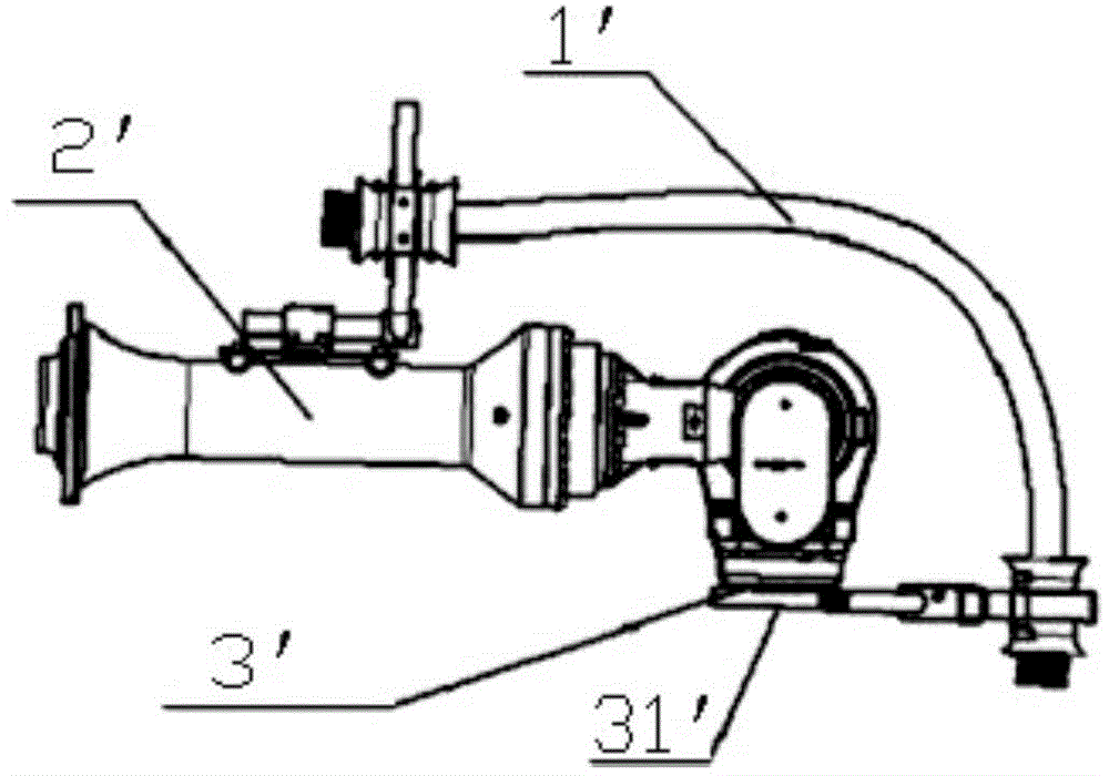
However, when the robot rotates around the axis of rotation, the pipeline is seriously twisted; moreover, the pipeline is completely exposed, with too much margin, and it is prone to scratches when rotating, which greatly reduces the service life of the pipeline

Method used


Image

  • Wiring structure of tail end executor of industrial robot
  • Wiring structure of tail end executor of industrial robot
  • Wiring structure of tail end executor of industrial robot

Examples


Embodiment Construction

[0024] Hereinafter, the present invention will be described in detail by using figures and words.

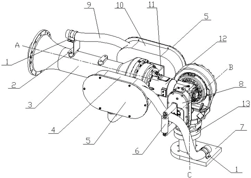
[0025] Such as figure 2 As shown, the present invention discloses a wiring structure of an end effector of an industrial robot, which includes a large body tube 3, a box body is respectively provided on both sides of the large body tube 3, and a wrist is connected to the rear end of the large body tube 3, and the wrist includes A body wrist joint forearm 12 and a body end wrist 8 at the rear end thereof, a flange 13 is provided on the body end wrist 8, a base 7 is provided on the flange 13, and at least one pipeline 9 is connected to the base 7 and the body cylinder 3 .

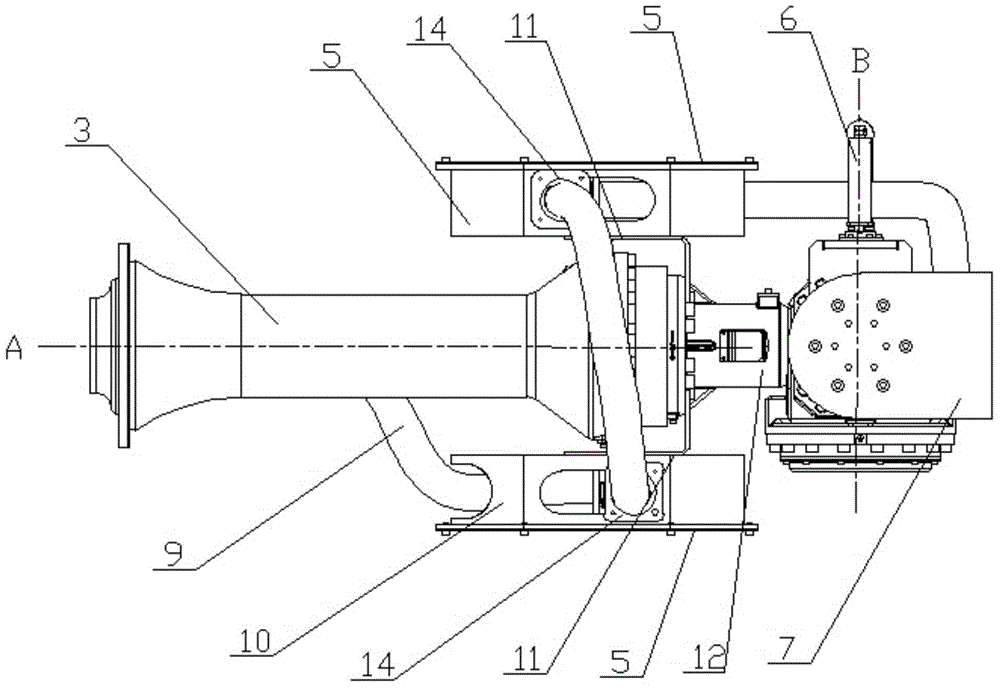
[0026] Such as figure 2 and image 3 As shown, a first box body 4 and a second box body 10 are arranged symmetrically on both sides of the main body cylinder 3, and the first box body 4 and the second box body 10 are installed on the wrist joint forearm 12 of the body body through a mounting bracket 11. A...


PUM


Abstract

The invention provides a wiring structure of a tail end executor of an industrial robot. The wiring structure comprises a large body cylinder, at least one box is arranged on the large body cylinder, a wrist portion is connected to the large body cylinder, the wrist portion can rotate around the large body cylinder, a pipeline is connected to the large body cylinder and the wrist portion, and the pipeline is partly contained in the box body. According to the wiring structure of the tail end executor of the industrial robot, the pipeline moves in the box body, and cannot be separated from the large body cylinder too far or scratch the large body cylinder, scratching generated by excessive twisting of the pipeline and too large motion range can be effectively avoided, and therefore the service life of the pipeline is prolonged.

Description

technical field [0001] The invention relates to a wire routing structure of an end effector of an industrial robot, in particular to a wire routing structure of an actuator wrist of an industrial robot that avoids twisting or scratching of pipelines. Background technique [0002] At present, the wiring methods used for the wrist wiring of industrial robot actuators are as follows: figure 1 As shown, after the pipeline 1' is connected from the beginning, one end is fixed on the large cylinder 2' of the robot body, and the other end is directly connected to the support 31' fixed on the flange 3' at the end of the robot body. However, when the robot rotates around the axis of rotation, the pipeline is severely twisted; moreover, the pipeline is completely exposed, with too much margin, and it is prone to scratches during rotation, which greatly reduces the service life of the pipeline. Therefore, it is necessary to design a better wiring arrangement of the robot actuator wrist...

Claims


Application Information

Patent Timeline
IPC IPC(8): B25J9/08B25J17/02
Inventor 何伟全曲道奎徐方李学威边弘晔冯亚磊
Owner SHENYANG SIASUN ROBOT & AUTOMATION
Learn More