A self-pressurized remote-controlled condensate oil sealed recovery process method and device

A process method and technology of condensate oil, which are applied in the valve device of wellbore/well, earth-moving drilling, sealing/packing, etc., can solve the problem of good volatility of condensate oil, danger of burning and unblocking, large safety risk, etc. problems, to achieve the effect of high-efficiency separation of gas and liquid, solving the blockage of condensate, and avoiding casualties

Active Publication Date: 2017-10-17
PETROCHINA CO LTD
View PDF6 Cites 0 Cited by
  • Summary
  • Abstract
  • Description
  • Claims
  • Application Information

AI Technical Summary

Problems solved by technology

[0004] 1. Direct discharge is an open recovery mode. Workers on the job can directly contact condensate oil. Because condensate oil is highly volatile, it is easy to accumulate in low-lying places. When employees operate in low-lying places, a large number of condensate oil particles may be attached to their clothes. , and the condensate oil has a low ignition point, which is prone to flash fire accidents after employees come up and cause casualties
[0005] 2. The gas used in the well site is connected from the outlet of the pressure cylinder. When the pressure cylinder fails to achieve the purpose of separation, the gas outlet pipeline is prone to condensate oil clogging
When the gas supply pipeline of the heating furnace is blocked, the intermittent gas supply to the burner may cause a condensate oil flash (explosion) accident, and there is a greater safety risk
[0006] 3. There is a certain danger in burning and unblocking

Method used


Image

  • A self-pressurized remote-controlled condensate oil sealed recovery process method and device
  • A self-pressurized remote-controlled condensate oil sealed recovery process method and device
  • A self-pressurized remote-controlled condensate oil sealed recovery process method and device

Examples


Embodiment 1

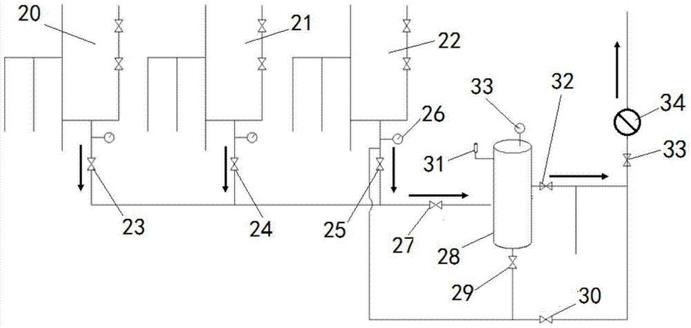
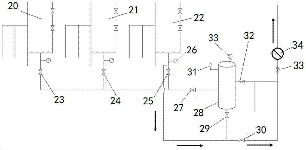
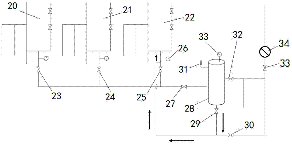
[0026] Embodiment 1: as figure 1 , figure 2 , image 3 and Figure 4 As shown, a self-pressurized remote control type condensate oil sealing recovery process device, the 1# oil well 20, the 2# oil well 21, and the 3# oil well 22 are respectively connected to the eighth gate 23, the seventh gate 24, and the sixth gate 25. The other ends of the eight gates 23, the seventh gate 24, and the sixth gate 25 are connected to the first gate 27, and the gas-liquid separator 28 is connected to the safety valve 31, the second gate 32, the third gate 29, the first gate 27 and Pressure gauge 33, the fifth gate 33 is connected to the flame arrester 34, the other end of the third gate 29 is connected to the other end of the sixth gate 25, the other end of the fourth gate 30, and one end of the fourth gate 30 is connected to the other end of the fifth gate 33 one end,

[0027] The 1# oil well 20 and the 2# oil well 21 are respectively connected to the oil well pressure gauge, and the 3# o...

Embodiment 2

[0029] Embodiment 2: as figure 1 , figure 2 , image 3 and Figure 4 As shown, a self-pressurized remote control type condensate oil closed recovery process method comprises the following steps;

[0030] Step 1. Associated gas normal venting process:

[0031] The associated gas produced by 1# oil well 20, 2# oil well 21, and 3# oil well 22 of oil wells merges into the first gate 27 after passing through the sixth gate 25, seventh gate 24, and eighth gate 23, and the other end of the first gate 27 Connected to the gas-liquid separator 28, the gas in the gas-liquid separator 28 goes up through the action of the coarse filter, multi-layer funnel and barrier ring, and the gas passes through the fine filter and is drawn out by the second gate 32 and the fifth gate 33 to the vent Torch, close the third gate 29 and the fourth gate 30 during the venting period; the liquid part generated in the gas-liquid separator 28 gathers to the lower layer to complete the entire separation pr...

Embodiment 3

[0037]Embodiment 3: A self-pressurized remote control type condensate oil sealing recovery process method, the gas-liquid separator can be installed on the concrete foundation 20m away from the well group, and the plane of the concrete foundation should be higher than the wellhead, so that the condensate oil can flow from When the liquid outlet flows out, it forms a slope with the wellhead, which is beneficial to self-pressure backflow. Place the direction of the gas-liquid separator according to the position of the associated gas interface, reserve the installation positions of the well gas pipeline, liquid pipeline, gas outlet pipeline, solenoid valve, gate and other components when placing it, and the direction of the gas outlet pipeline is installed and connected to the vent pipeline. The concrete platform is slightly larger than the length and width of the device, and should be higher than the surrounding ground by more than 200mm, so as to prevent rain from flooding the f...


PUM


Abstract

The invention provides a self-pressure remote-control gas condensate closed recycling process method and device, and belongs to the technical field of oilfield associated gas recycling and exhaust processes. A pressure gauge connector is connected with the top end of a housing; the upper end of the housing is connected with a safety valve connector, and a gas outlet; a fine filter net is connected with the inner cavity of the housing; the bottom end of the fine filter net is connected with a liquid guide pipe; a liquid outlet is formed in the bottom end of the liquid guide pipe; the lower end of the housing is connected with a gas inlet; the lower part of the inner cavity of the housing is connected with a coarse filter net and a water-gas partition; and the lower part of the fine filter net is connected with a filter element. In the process, gas condensate is recycled in a completely closed manner, and flows back to an oil well casing by adopting the pressure of a gas-liquid separator, and the gas-liquid separator is adopted to replace an original pressure cylinder, so that efficient gas-liquid separation is realized, and the problem that a gas outlet pipeline is blocked by gas condensate is solved. Therefore, the safety risk of gas condensate flash burning (explosion) is avoided.

Description

technical field [0001] The invention relates to a self-pressurized remote control type condensate oil closed recovery process method and device, belonging to the technical field of recovery and discharge process of oil field associated gas. Background technique [0002] With the continuous growth of oil and natural gas consumption demand, my country's oil and natural gas extraction volume is also rising. Oil wells are often accompanied by associated gas production during the production process. During the recovery and utilization of associated gas or the discharge and combustion process, a large amount of heavy hydrocarbons will be precipitated, which is called condensate. Its main component is C 5 to C 8 A mixture of hydrocarbons, highly volatile, flammable and explosive. [0003] At present, associated gas is commonly used to heat well groups with sufficient associated gas in oilfield production. During the use of associated gas, a small amount of condensate oil is prod...

Claims


Application Information

Patent Timeline
Patent Type & Authority Patents(China)
IPC IPC(8): E21B43/00E21B34/08E21B43/34
CPCE21B34/08E21B43/00E21B43/34
Inventor 赵晓龙杨仓海李永长魏小林于世春操红梅李丽邱亮张彬邱奇白晓红
Owner PETROCHINA CO LTD
Why Eureka
Try Eureka