Eureka AIR delivers breakthrough ideas for toughest innovation challenges, trusted by R&D personnel around the world.

Hard and brittle shale microfracture manufacturing method and plugging capability testing system

A production method and mud shale technology, which is applied in earthwork drilling, sealing/isolation, wellbore/well components, etc., can solve the problems of large difference and the inability to truly simulate the change process of hard and brittle mud shale and plugging process

Inactive Publication Date: 2015-05-20
BC P INC CHINA NAT PETROLEUM CORP +1
View PDF6 Cites 19 Cited by
  • Summary
  • Abstract
  • Description
  • Claims
  • Application Information

AI Technical Summary

Problems solved by technology

However, there is a large gap between them and the real environment of hard and brittle mud shale under high temperature and high pressure conditions at the bottom of the well, and the material and fracture surface characteristics are quite different from those of real mud shale, so it is impossible to truly simulate the hard and brittle mud shale under high temperature and high pressure conditions. The changing process of drilling fluid and the sealing process of fractures

Method used


Image

  • Hard and brittle shale microfracture manufacturing method and plugging capability testing system
  • Hard and brittle shale microfracture manufacturing method and plugging capability testing system
  • Hard and brittle shale microfracture manufacturing method and plugging capability testing system

Examples


Embodiment 1

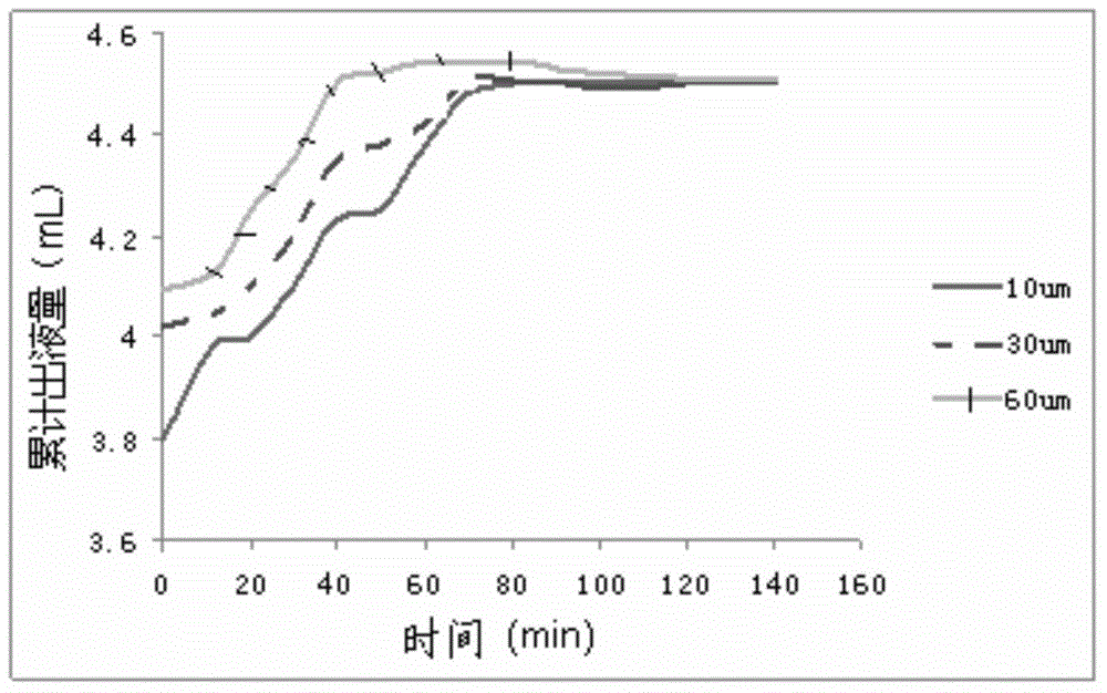
[0051] According to the operation steps, rock samples with crack widths of 10 μm, 30 μm and 60 μm were prepared, and three parts of water-based drilling fluid were prepared indoors, and 3% sulfonated asphalt was added to them. Use the test system of the present invention to carry out the plugging test experiments of 10 μm, 30 μm and 60 μm rock samples respectively according to the test steps, record the cumulative liquid output respectively, and make a curve graph, such as: image 3 shown.

[0052] from the curve image 3 It can be seen that the same drilling fluid formulation has different plugging effects on micro-fractures of different widths. The larger the fracture width, the greater the initial and cumulative fluid production. After 80 minutes, the graphs tend to be stable, indicating that the drilling fluid formulation has effectively plugged the fractures. After the experiment, the rubber sleeve was cut, and the invasion depth and accumulation of the mud cake in the ...

Embodiment 2

[0054] According to the operation steps, three rock samples with a crack width of 50 μm were prepared, and three water-based drilling fluids were prepared indoors, and 1%, 3%, and 5% of sulfonated asphalt were added to them respectively. Use the test system of the present invention to test the plugging ability of drilling fluids with different concentrations according to the test steps, record the accumulated liquid output, and make a graph, such as: Figure 4 shown.


PUM


Abstract

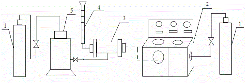
The invention relates to the technical field of petroleum exploration and development experimental facilities, in particular to a hard and brittle shale microfracture manufacturing method and a plugging capability testing system. The testing system comprises a stable gas source, a high-temperature and high-pressure dynamic displacement device, a shale sample clamp, an outlet liquid receiving device and a circulating press pump, wherein the stable gas source is connected with the high-temperature and high-pressure dynamic displacement device through a section of high-pressure pipeline, the shale sample clamp is used for clamping a shale sample to be tested and is connected with the high-temperature and high-pressure dynamic displacement device through screw threads, the outlet liquid receiving device is connected with the outlet end of the shale sample clamp through a valve, the circulating press pump is connected with the shale clamp through a high-pressure pipeline, and stable pressure is provided as the pressure of the circulating press pump through the stable gas source. The manufacturing method and the plugging capacity testing system can be used for plugging agent preference selection experiments and drilling liquid plugging capability test experiments, and a reliable testing means is provided for the researches of the well wall stability of a hard and brittle shale stratum.

Description

technical field [0001] The invention relates to the technical field of experimental equipment and methods for petroleum exploration and development, in particular to a method for making micro-cracks in hard and brittle mud shale and a testing system for plugging ability. Background technique [0002] At present, wellbore instability has caused at least about 600 million US dollars of losses to the world oil industry every year, and the time consumed is about 5% to 6% of the total drilling time. According to statistics, mud shale formations account for 70% of the total drilled formations, and more than 90% of the wellbore instability problems occur in the mud shale formations, of which about two-thirds of the wellbore instability problems occur in Hard and brittle shale formations. This is due to the development of micro-fractures in hard and brittle mud shale, which not only hydrates and expands when exposed to water, but also migrates with the fluid, especially after the...

Claims


Application Information

Patent Timeline
Patent Type & Authority Applications(China)
IPC IPC(8): E21B49/00E21B33/13
CPCE21B49/00E21B33/13
Inventor 侯杰刘永贵宋广顺宋涛李海赵亚涛孙宪军
Owner BC P INC CHINA NAT PETROLEUM CORP
Why Eureka
Eureka Blog
Learn More