Two-stage enthalpy-increasing rotor compressor and air conditioner

A rotor type, compressor technology, applied in the direction of machine/engine, rotary piston type/oscillating piston type pump components, and elastic fluid rotary piston type/oscillating piston type pump combination, etc., can solve the problem of reducing the performance of refrigeration system. , secondary compression power increase, poor exhaust and other problems, to achieve the effect of improving air supply efficiency, suppressing pressure fluctuations, and preventing cross flow

Active Publication Date: 2015-05-20
ZHUHAI GREE REFRIGERATION TECH CENT OF ENERGY SAVING & ENVIRONMENTAL PROTECTION
View PDF6 Cites 11 Cited by
  • Summary
  • Abstract
  • Description
  • Claims
  • Application Information

AI Technical Summary

Problems solved by technology

In the prior art, the intermediate chamber is a chamber where the first-stage compressed exhaust gas is mixed with supplementary air. Since the rotor compressor absorbs and exhausts air at a non-uniform rate, the gas pressure fluctuation in the intermediate chamber is very obvious.
The fluctuation of the refrigerant pressure in the intermediate chamber often leads to poor exhaust of the low-pressure stage cylinder and large loss through the compressor; the suction pressure of the high-pressure stage cylinder is low, the secondary compression pressure ratio increases, and the secondary compression power increases; at the same time , in the stage of the peak pressure of the intermediate chamber, the pressure in the intermediate chamber is higher than the air supply pressure, resulting in the backflow of the air supply, which reduces the performance of the refrigeration system; the excessive pressure fluctuation of the intermediate chamber causes the air flow noise of the compressor to be large

Method used


Image

  • Two-stage enthalpy-increasing rotor compressor and air conditioner
  • Two-stage enthalpy-increasing rotor compressor and air conditioner
  • Two-stage enthalpy-increasing rotor compressor and air conditioner

Examples


Embodiment Construction

[0017] In order to make the purpose, technical solution and advantages of the present invention clearer, the two-stage enthalpy-increasing rotary compressor and air conditioner of the present invention will be further described in detail below in conjunction with the accompanying drawings and embodiments. It should be understood that the specific embodiments described here are only used to explain the present invention, not to limit the present invention.

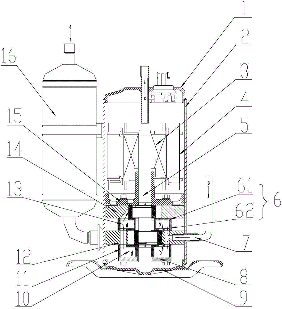
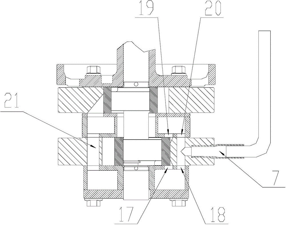
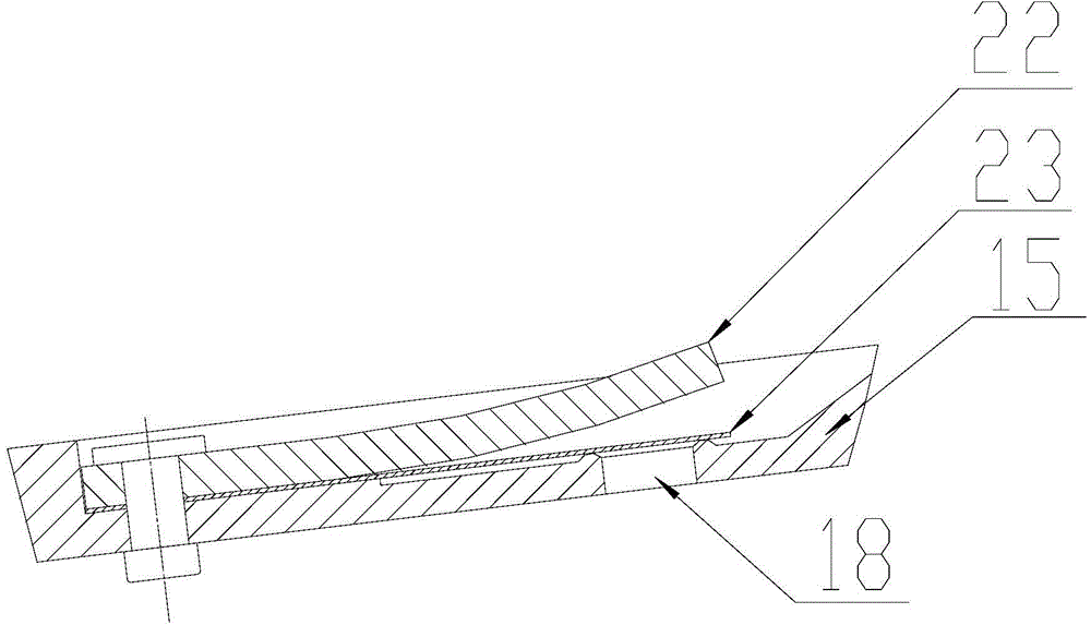
[0018] refer to Figure 1 to Figure 3 , an embodiment of the two-stage enthalpy-increasing rotary compressor of the present invention includes a high-pressure stage cylinder 14, a low-pressure stage cylinder 12, a middle cover plate assembly 6, a lower flange 11 and a lower cover plate 8, a high-pressure stage cylinder 14, a middle cover plate Component 6, low-pressure stage cylinder 12, lower flange 11 and lower cover plate 8 are arranged sequentially from top to bottom, low-pressure stage cylinder 12 is used as the first-...


PUM


Abstract

The invention provides a two-stage enthalpy-increasing rotor compressor. The two-stage enthalpy-increasing rotor compressor comprises a high-pressure-stage air cylinder, a middle cover plate assembly, a low-pressure-stage air cylinder, a lower flange and a lower cover plate, which are sequentially arranged from top to bottom, wherein the low-pressure-stage air cylinder is used as a primary compression cylinder, and the high-pressure-stage air cylinder is used as a secondary compression cylinder; a first middle cavity is formed inside the middle cover plate assembly, a second middle cavity is formed between the lower flange and the lower cover plate, the first middle cavity is communicated with the second middle cavity, a first exhaust opening and a first air replenishing opening are formed in the first middle cavity, and a second exhaust opening and a second air replenishing opening are formed in the second middle cavity; the first exhaust opening is communicated with an upper exhaust incision of the low-pressure-stage air cylinder, the second exhaust opening is communicated with a lower exhaust incision of the low-pressure-stage air cylinder, the first air replenishing opening and the second air replenishing opening are communicated with an enthalpy increasing opening of the low-pressure-stage air cylinder, and the first middle cavity is communicated with an air suction opening of the high-pressure-stage air cylinder. The invention also relates to an air conditioner. By adopting the two-stage enthalpy-increasing rotor compressor and the air conditioner, the volume of the middle cavity is increased, the fluctuation of the pressure of the middle cavity is effectively prevented, and the air replenishing efficiency is high.

Description

technical field [0001] The invention relates to the refrigeration field, in particular to a two-stage enthalpy-increasing rotor compressor and an air conditioner. Background technique [0002] Due to its high efficiency, good reliability, wide temperature range and other application characteristics, the two-stage enthalpy-increasing rotary compressor has been more and more widely used in the fields of low-temperature heating and high-temperature refrigeration. In the prior art, the intermediate chamber is a chamber in which the first-stage compression exhaust gas is mixed with supplementary air. Since the rotary compressor sucks and exhausts air at a non-uniform rate, the gas pressure fluctuation in the intermediate chamber is very obvious. The fluctuation of the refrigerant pressure in the intermediate chamber often leads to poor exhaust of the low-pressure stage cylinder and large loss through the compressor; the suction pressure of the high-pressure stage cylinder is low,...

Claims


Application Information

Patent Timeline
Patent Type & Authority Applications(China)
IPC IPC(8): F04C23/00F04C29/00
CPCF04C23/001F04C29/065F04C29/12F04C29/126
Inventor 余冰魏会军杨欧翔
Owner ZHUHAI GREE REFRIGERATION TECH CENT OF ENERGY SAVING & ENVIRONMENTAL PROTECTION
Why Eureka
Try Eureka