Shaft coupling structure of calendaring machine

A calender, coupling technology, applied in the direction of coupling, rigid shaft coupling, mechanical equipment, etc., can solve the problem of reducing the coaxiality of the output shaft and the connecting shaft assembly, and inconvenient maintenance and replacement of the coupling or shaft , Reduce the service life of the coupling or shaft, etc., to achieve the effect of convenient and simple disassembly and maintenance, improve service life, and reduce wear and tear

Inactive Publication Date: 2015-05-20
WUXI HOUZHAI ZHENXIN MACHINERY
View PDF0 Cites 2 Cited by
  • Summary
  • Abstract
  • Description
  • Claims
  • Application Information

AI Technical Summary

Problems solved by technology

[0002] The existing shaft coupling of the calender includes two connecting pieces with similar structures. The flange parts at the axial ends of the two connecting pieces are connected and fastened by adding bolts and nuts. The keyway, when assembling, the shaft and the shaft hole on the coupling adopt an interference fit, the maintenance and replacement of the coupling or shaft is inconvenient, and after many times of assembly and disassembly, the reduction of the interference will affect the co

Method used


Image

  • Shaft coupling structure of calendaring machine

Examples


Embodiment Construction

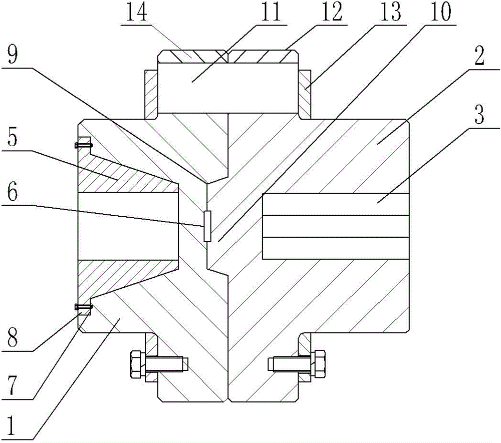
[0010] Such as figure 1 As shown, the coupling structure of the calender includes a connecting piece 1 and a connecting piece 2. The axial inner end surface of the connecting piece 2 is provided with a tapered bump 10, and the axial direction of the connecting piece 1 is The inner end surface is provided with a tapered groove 9 that cooperates with the tapered pin protrusion 10, and the end surface where the tapered protrusion 10 and the tapered groove 9 fit together is provided with a flat key 6, and the flanges of the first connector 1 and the second connector 2 The parts 14 and 12 are connected by nylon pins 11, the connecting piece 1 and the connecting piece 2 are respectively sleeved with a pressure plate 13, the inner end surface of the pressure plate 13 is pressed on the outer end surface of the column pin 11, and the pressure plate 13 and the flange part 12, 14 is fixed by bolts, the radius of the pressure plate 13 is smaller than the axial distance between the column ...


PUM


Abstract

The invention provides a shaft coupling structure of a calendaring machine. The shaft coupling structure of the calendaring machine has the advantages that the disassembly and the maintenance are simple and convenient, the coaxiality of shaft assembling can be guaranteed, and the service life is improved. The shaft coupling structure of the calendaring machine comprises a first connecting piece and a second connecting piece. The shaft coupling structure of the calendaring machine is characterized in that a cone-shaped convex block is arranged on the axial inner side end face of the second connecting piece in an external convex mode, and a cone-shaped groove matched with the cone-shaped convex block is formed in the axial inner side end face of the first connecting piece; a flat key is arranged on the end face where the cone-shaped convex block is attached to the cone-shaped groove, the flange portion of the first connecting piece is connected with the flange portion of the second connecting piece through a pin, the first connecting piece and the second connecting piece are both provided with a pressing plate in a sleeved mode, and the inner side end faces of the pressing plates are arranged on the outer side end faces of the pin in a pressing mode; first connecting holes are both in the shape of a cone, and the larger radial end face of each connecting hole is located at the outer side of the first connecting piece; a cone-shaped sleeve is arranged in the corresponding connecting hole in a matched mode, and motor output shafts of the calendaring machine are arranged in axial mounting holes of the cone-shaped sleeves respectively.

Description

technical field [0001] The invention relates to a shaft connection device of a calender, in particular to a shaft coupling structure of a calender. Background technique [0002] The existing shaft coupling of the calender includes two connecting pieces with similar structures. The flange parts at the axial ends of the two connecting pieces are connected and fastened by adding bolts and nuts. The keyway, when assembling, the shaft and the shaft hole on the coupling adopt an interference fit, the maintenance and replacement of the coupling or shaft is inconvenient, and after many times of assembly and disassembly, the reduction of the interference will affect the coaxiality of the shaft assembly , Secondly, the wear of the coupling of the calender mostly occurs on the connecting piece that cooperates with the output shaft of the motor, and then the bolt is threaded with the flange, and the thread wear after long-term use will increase the axial misalignment of the coupling. S...

Claims


Application Information

Patent Timeline
IPC IPC(8): F16D1/033
Inventor 王惠峰
Owner WUXI HOUZHAI ZHENXIN MACHINERY
Why Eureka
Try Eureka