Air pressure damping mechanism and air pressure damping shock absorber with the same

A technology of damping mechanism and shock absorber, applied in the direction of shock absorber, gas shock absorber, spring/shock absorber, etc. The shock effect is stable, the damping force is improved, and the protection is not damaged.

Inactive Publication Date: 2015-05-20
常州市达文电动车辆配件厂
View PDF9 Cites 4 Cited by
  • Summary
  • Abstract
  • Description
  • Claims
  • Application Information

AI Technical Summary

Problems solved by technology

[0005] The object of the present invention is to overcome the deficiencies of poor damping force and poor rebound performance of the existing air pressure shock absorber, provide a kind of air pressure damping mechanism and the air pressure damping shock absorber using the mechanism, adopt the air pressure damping shock absorber of the present invention The technical solution uses the damping effect of the gas medium in the damping hole of the damping piston to greatly increase the damping force of the gas medium, making the air pressure damping effect more stable, and can be used for damping in structures such as shock absorbers or gas springs; The shock absorber of the air pressure damping mechanism of the present invention has better downward pressure and rebound performance, and does not need to use springs, which greatly improves the driving comfort; it adopts pure gas power, no shock absorber oil, avoids oil leakage, and has a relatively simple structure , and can realize automatic inflation function, the gas pressure is not limited by high temperature and low temperature, especially suitable for front and rear shock absorption of bicycles, electric vehicles and motorcycles, and can also be used in other industries that play a role in shock absorption

Method used


Image

  • Air pressure damping mechanism and air pressure damping shock absorber with the same
  • Air pressure damping mechanism and air pressure damping shock absorber with the same
  • Air pressure damping mechanism and air pressure damping shock absorber with the same

Examples


Embodiment

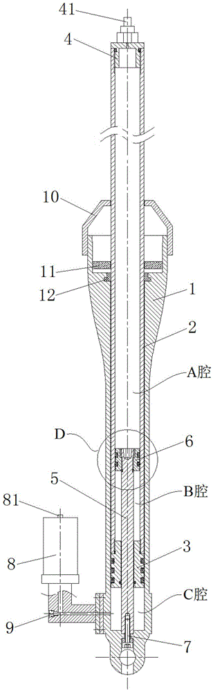
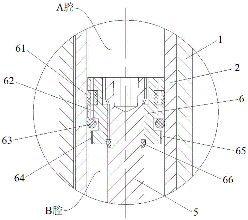
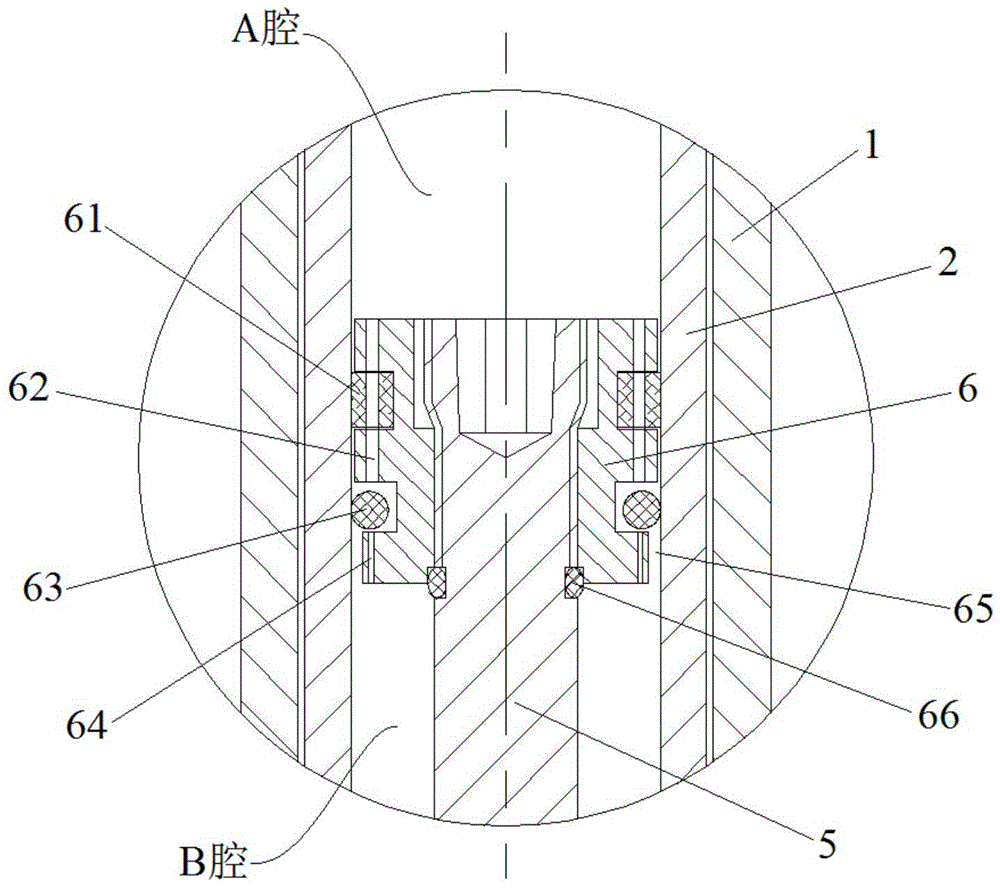
[0034]As shown in Fig. 2, a kind of air pressure damping mechanism of this embodiment includes a handle tube 2 and a piston rod 5 arranged in the handle tube 2, both ends of the handle tube 2 are sealed, and the handle tube 2 is filled with gas, which can It can be air or a mixed gas. One end of the piston rod 5 located in the handle tube 2 is provided with a damping piston 6. The damping piston 6 divides the handle tube 2 into an A chamber and a B chamber. The A chamber is a rodless chamber, and the B chamber It is a rod cavity, and the structure is similar to the cylinder structure, the difference is that the handle tube 2 is a sealed space, and the damping piston 6 has a good gas damping effect; specifically, the damping piston 6 is provided with a sealing ring installation groove, and the sealing ring A floating sealing ring 63 is arranged in the installation groove, and the size of the sealing ring installation groove is appropriately larger than the floating sealing ring ...


PUM


Abstract

The invention discloses an air pressure damping mechanism and an air pressure damping shock absorber with the same and belongs to the field of shock absorbers. The air pressure damping mechanism comprises a handle tube and a piston rod, the handle tube is filled with gas, a damping piston is arranged at the end, located in the handle tube, of the piston rod, and the handle tube is divided into a cavity A and a cavity B through the damping piston. A floatation sealing ring installed in a sealing ring installation groove is arranged on the damping piston, a first damping hole and a second damping hole for the sealing ring installation groove to be communicated with the cavity A and the cavity B are formed in the damping piston, the hole diameter of the first damping hole is larger than that of the second damping hole, and a gap for the cavity B and the sealing ring installation groove to be communicated is further arranged between the damping piston and the handle tube. According to the air pressure damping mechanism and the air pressure damping shock absorber with the same, the damping force of gas media is improved, and the air pressure damping effect is more stable. By means of the shock absorber with the air pressure damping mechanism, the downward pressing and rebounding performance is better, and the driving comfort is greatly improved.

Description

technical field [0001] The invention relates to a damping mechanism and a shock absorber, more specifically, to an air pressure damping mechanism and an air pressure damping shock absorber using the same. Background technique [0002] In order to alleviate and attenuate the impact and vibration of the motorcycle due to the unevenness of the road during driving, to ensure the smoothness and comfort of driving, and to improve the service life of the motorcycle and the stability of the operation, the motorcycle is equipped with a shock absorber. vibrator. Existing motorcycle shock absorbers can be roughly divided into spring shock absorbers, spring-air damping shock absorbers, hydraulic damping shock absorbers, and oil-air combined front fork shock absorbers according to the working medium. and nitrogen-filled hydraulic shock absorbers, etc. The existing spring-type shock absorber can withstand a large load, but there is a phenomenon of self-vibration, which easily transmits ...

Claims


Application Information

Patent Timeline
Patent Type & Authority Applications(China)
IPC IPC(8): F16F9/02F16F9/34
CPCF16F9/0209F16F9/0281F16F9/368F16F9/43
Inventor 许伟
Owner 常州市达文电动车辆配件厂
Why Eureka
Try Eureka