Vane-guided high-pressure series spool structure

A oriented, valve core technology, applied in the direction of lift valve, valve device, engine components, etc., can solve the problems of sticking, clogging, affecting the normal use of the valve, etc., to avoid breakage, enhance reliability, and prolong service life.

Active Publication Date: 2017-04-12
WUXI SMART AUTO CONTROL ENG CO LTD
View PDF5 Cites 0 Cited by
  • Summary
  • Abstract
  • Description
  • Claims
  • Application Information

AI Technical Summary

Problems solved by technology

At present, most of the methods to solve such problems in the prior art adopt a labyrinth structure and an orifice structure, although the above two solutions can meet the requirements of noise reduction and speed reduction, and at the same time meet the requirements of reducing flashing, cavitation and other phenomena. , but when the medium contains a large number of particles, or the medium viscosity is too high, both the labyrinth structure and the orifice structure are prone to coking, sticking, and clogging, which will affect the normal use of the valve.

Method used


Image

  • Vane-guided high-pressure series spool structure
  • Vane-guided high-pressure series spool structure

Examples


Embodiment Construction

[0016] The present invention will be further described below in conjunction with specific drawings.

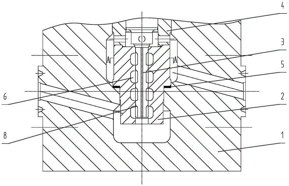
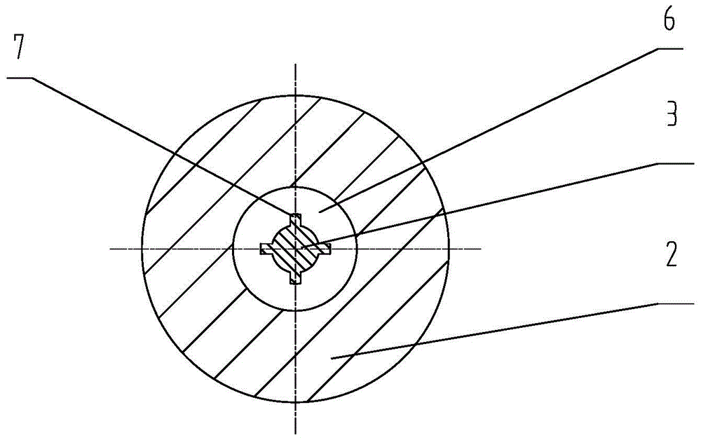
[0017] Such as Figure 1 ~ Figure 2 As shown: the vane-guided high-pressure series valve core structure includes valve body 1, valve seat 2, series valve core 3, guide sleeve 4, sealing gasket 5, flow hole 6, vane 7, regulating surface 8, etc. .

[0018] Such as figure 1 As shown, the present invention includes a valve body 1, a valve seat 2 is installed in the valve body 1, a series valve core 3 is installed in the valve seat 2, a guide pressure sleeve 4 is fixed on the valve seat 2 top, and the series valve core 3 passing through the guide pressure sleeve 4; a sealing gasket 5 is installed between the valve body 1 and the valve seat 2 to play the function of sealing the valve seat 2;

[0019] Such as figure 1 , figure 2 As shown, a plurality of flow holes 6 are formed from bottom to top along the inner cavity of the valve seat 2, and the inner diameter of the flow hole...


PUM


Abstract

The invention relates to a vane guiding high-pressure string-type valve core structure. The vane guiding high-pressure string-type valve core structure comprises a valve body, a valve seat is mounted in the valve body, a string-type valve core is disposed in the valve seat, and a guiding pressure sleeve is fixed on the upper portion of the valve seat. The vane guiding high-pressure string-type valve core structure is characterized in that a plurality of circulating holes are formed from bottom to top along an inner cavity of the valve seat, inner diameter of the circulating holes is larger than that of the inner cavity of the valve seat, the string-type valve core penetrates the circulating holes, a plurality of vanes are distributed on the string-type valve core, outer circles of the vanes are tightly matched with the inner cavity of the valve seat, transition between lower ends of the vanes and the outer surface of the string-type valve core is achieved by means of first section circular arcs, transition between the lower ends of the vanes and upper ends of the vanes is achieved by means of second section circular arcs, the first section circular arcs and the second section circular arcs form adjusting curved surfaces, lengths of adjusting curved surfaces of all vanes are equal, and the top of the string-type valve core and the top of the inner cavity of the valve seat are sealed by means of a conical sealing surface. By means of the vane guiding high-pressure string-type valve core structure, phenomena of fluid flash evaporation and cavitation can be effectively reduced, washing of media to valve trim is decreased, and noise is reduced.

Description

technical field [0001] The invention relates to a regulating valve spool structure, in particular to a vane-guided high-pressure series spool structure suitable for high-pressure differential and granular medium working conditions. Background technique [0002] With the development of petrochemical, coal chemical, thermal power plant, nuclear power plant and other industries for fluid pressure to a higher pressure drop, the valve is prone to flashing, cavitation, valve stem fracture and other phenomena under this working condition. At present, most of the methods to solve such problems in the prior art adopt a labyrinth structure and an orifice structure, although the above two solutions can meet the requirements of noise reduction and speed reduction, and at the same time meet the requirements of reducing flashing, cavitation and other phenomena. , but when the medium contains a large number of particles or the medium viscosity is too high, both the labyrinth structure and ...

Claims


Application Information

Patent Timeline
Patent Type & Authority Patents(China)
IPC IPC(8): F16K1/36
CPCF16K1/36
Inventor 陈彦陆坤铭盛子烨袁水
Owner WUXI SMART AUTO CONTROL ENG CO LTD
Why Eureka
Try Eureka