Quadratic element imager

An imager, two-dimensional technology, applied in instruments, measuring devices, optical devices, etc., can solve the problems of wasting adjustment time, difficult to accurately position the workpiece, unable to take into account both rapid movement adjustment and precise movement adjustment, etc., to achieve rapid movement adjustment. , Reasonable design, accurate movement adjustment and positioning effect

Active Publication Date: 2015-05-20
东莞市乾丰电子科技有限公司
View PDF7 Cites 0 Cited by
  • Summary
  • Abstract
  • Description
  • Claims
  • Application Information

AI Technical Summary

Problems solved by technology

The moving device usually moves the stage at a constant speed. If the speed is too fast, the adjustment time can be saved, but it is not easy to position the workpiece accurately; if the s...

Method used


Image

  • Quadratic element imager
  • Quadratic element imager
  • Quadratic element imager

Examples


Embodiment

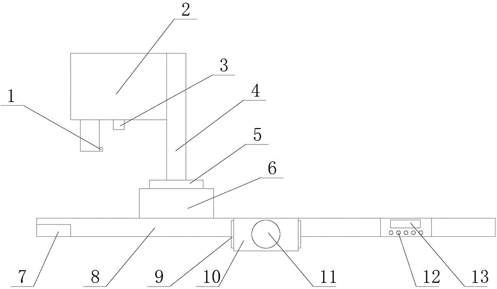
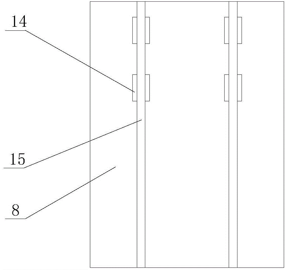
[0020] Such as Figure 1-3 As shown, the two-dimensional imager includes a lens, and the lens is installed on a connecting frame 2, and the connecting frame 2 is installed on a column 4. The column 4 is installed on the rotating mechanism, and the rotating mechanism is installed on the bottom plate 8 through the carrier 6 . The bottom plate 8 is provided with a plurality of parallel chute 15, and a moving mechanism is installed in the chute 15, and the moving mechanism is connected with a transmission mechanism.

[0021] The rotating mechanism includes a rotating motor installed on the platform, and the rotating motor is connected to the column through transmission. In addition, in addition to the above-mentioned use of the rotating motor as the rotating mechanism, it can also be designed in the form of a cylinder and a rotating disk, and the purpose of rotation can also be achieved.

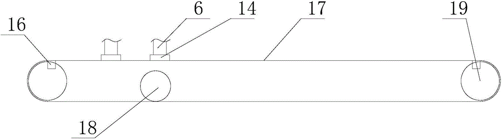
[0022] The moving mechanism includes gears 19 installed at both ends of the chute 15 , and...


PUM


Abstract

The invention discloses a quadratic element imager, and belongs to the field of imager equipment. The quadratic element imager comprises a lens, wherein the lens is arranged on a connection frame; the connection frame is arranged on a stand column; the stand column is arranged on a rotary mechanism; the rotary mechanism is arranged on a bottom plate through a platform deck; a plurality of sliding chutes which are parallel with each other are formed in the bottom plate; moving mechanisms are arranged in the sliding chutes; the moving mechanisms are connected with a transmission mechanism. The quadratic element imager is reasonable in design, is easy to operate, can be moved and adjusted conveniently and rapidly, and has a higher industrial application value; the aims of accurately moving, adjusting and positioning are fulfilled.

Description

technical field [0001] The invention belongs to the field of imager equipment, and in particular relates to a two-dimensional imager. Background technique [0002] When the imager measures the workpiece, it is often necessary to adjust the position of the workpiece. Directly moving the workpiece by hand will cause contamination to the workpiece. In order to adjust the position of the workpiece, a moving device is usually used to move the carrier carrying the workpiece. The moving device usually moves the stage at a constant speed. If the speed is too fast, the adjustment time can be saved, but it is not easy to position the workpiece accurately; if the speed is too slow, a lot of adjustment time will be wasted while positioning the workpiece accurately, so , it is impossible to take into account both fast movement adjustment and precise movement adjustment. [0003] In view of the above defects, the designer actively researches and innovates, in order to create a two-dimens...

Claims


Application Information

Patent Timeline
IPC IPC(8): G01B11/00
Inventor 顾志卓
Owner 东莞市乾丰电子科技有限公司
Why Eureka
Try Eureka