Revolving shaft calibration method under binocular vision

A technology of binocular vision and calibration method, applied in the field of computer vision, can solve the problems of low calibration efficiency and complex calibration device.

Inactive Publication Date: 2015-05-20
XIAN UNIV OF TECH
View PDF5 Cites 21 Cited by
  • Summary
  • Abstract
  • Description
  • Claims
  • Application Information

AI Technical Summary

Problems solved by technology

[0006] The purpose of the present invention is to provide a method for calibrating the rotating shaft under binocular vision, which solves the problems in the

Method used


Image

  • Revolving shaft calibration method under binocular vision
  • Revolving shaft calibration method under binocular vision
  • Revolving shaft calibration method under binocular vision

Examples


Embodiment Construction

[0073] The present invention will be described in detail below in conjunction with the accompanying drawings and specific embodiments.

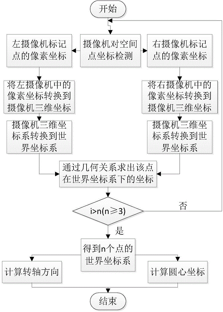
[0074] The present invention provides a method for calibrating the rotating shaft under binocular vision, such as figure 1 As shown, the specific steps are as follows:

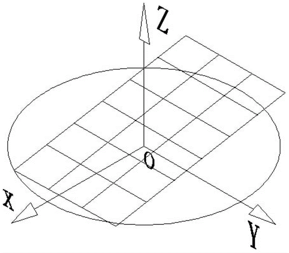
[0075] Step 1, place the rotating platform in the field of view of the two cameras, and place the calibration plate on the rotating platform; record the two cameras as the left camera and the right camera respectively; where the positioning of the calibration plate depends on The relative position of the two cameras and the rotary table, when placing the calibration board, it is necessary to ensure that the calibration board as a whole is within the common field of view of the two cameras before and after the rotation of the rotary table, and the corner points of the checkerboard can be detected. , when the camera lens is higher than the plane of the turntable, the calibrati...


PUM


Abstract

The invention discloses a revolving shaft calibration method under binocular vision. The method comprises the following steps: placing a rotating platform into the visual fields of two cameras, and placing a calibration board on the rotating platform; detecting the angular points of the calibration board by using two cameras simultaneously, and marking an angular point which is farthest away from the center of the rotating platform as a mark point Q1; rotating the rotating platform by two angles in sequence to obtain a mark point Q2 and a mark point Q3; solving the three-dimensional coordinates of the three mark points in a world coordinate system respectively; converting the geometrical relation between the revolving shaft and a rotating platform plane into an operation relation among vectors, and solving the direction of a revolving shaft and the circle center coordinate of the rotating platform according the three-dimensional coordinates of any two mark points obtained in the step 3 in order to finish the calibration of the revolving shaft. By adopting the revolving shaft calibration method under binocular vision, the problem of low calibration efficiency due to complexity of a calibration device and the requirement of acquisition of the mark points by means of a large amount of calculation in the prior art is solved.

Description

technical field [0001] The invention belongs to the technical field of computer vision, and relates to a rotating shaft calibration method under binocular vision. Background technique [0002] Binocular vision is based on the principle of parallax and uses imaging equipment to obtain two images of the measured object from different positions, and obtains the three-dimensional geometric information of the object by calculating the position deviation between the corresponding points of the image. The binocular measurement technology based on binocular vision is an important form of machine vision. It uses two cameras to simulate the structure of the human eye to measure the spatial feature points. It fuses the images obtained by the two eyes and observes the distance between them. The difference can obtain an obvious sense of depth, establish the correspondence between features, and correspond to the image points of a point in space in different images. In the binocular measu...

Claims


Application Information

Patent Timeline
IPC IPC(8): G01B11/00G01B11/245
Inventor 隋连升张毅坤支煜王凯张苓苓王娜
Owner XIAN UNIV OF TECH
Why Eureka
Try Eureka