System and method for performing foreign matter inspection on upper surface of ultrathin glass substrate

A glass substrate and ultra-thin glass technology, which is applied in the direction of material analysis, measuring device, and instrument by optical means, can solve the problems of misjudging the size and quantity of particles on the upper surface, reducing the yield rate, and being expensive. Incident angle, reduce false positive rate, reduce the effect of image acquisition area

Inactive Publication Date: 2015-05-20
TUNGHSU GRP
View PDF6 Cites 13 Cited by
  • Summary
  • Abstract
  • Description
  • Claims
  • Application Information

AI Technical Summary

Problems solved by technology

[0004] As the thickness of the display glass substrate becomes thinner and thinner (≤0.3mm), during the actual inspection, due to the thinner glass substrate thickness, the light transmittance is stronger, and the depth of field of the camera lens is difficult to further reduce, and expensive
In addition, when a diffuse light source emitted at a high inclination angle is used, since the light transmits through the glass substrate, if there is a defect on the lower surface and is within the scanning range of the line array camera, when the light irradiates the particles and diffuse reflection occurs, the line array camera will also reflect the light below. Particles on the surface are included in the detection results of the upper surface, causing the size and quantity of the particles on the upper surface to be misjudged, which virtually reduces the yield

Method used


Image

  • System and method for performing foreign matter inspection on upper surface of ultrathin glass substrate
  • System and method for performing foreign matter inspection on upper surface of ultrathin glass substrate

Examples


Embodiment Construction

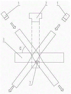
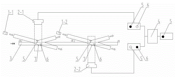
[0017] A system for inspecting foreign matter on the upper surface of an ultra-thin glass substrate. The structure includes a light source device 1 for illuminating the upper surface of a glass substrate 3, an imaging device, and an industrial computer 4 equipped with a management program. The key lies in: the light source device 1 The incident angle α of the emitted incident light on the upper surface of the glass substrate 3 is not greater than 45°, and the two supporting sets of imaging devices are symmetrically arranged on the upper and lower sides of the glass substrate 3, and are respectively attached to the glass substrate 3 by means of reflected light and refracted light. , the foreign matter on the lower surface, and transmit the digitized data to the industrial computer 4, and the industrial computer 4 uses the management program to compare the strength and weakness of the gray value of the two sets of imaging to form a system conclusion.

[0018] The light source dev...


PUM

PropertyMeasurementUnit
angle of incidenceaaaaaaaaaa

Abstract

The invention discloses a system for performing foreign matter inspection on the upper surface of an ultrathin glass substrate. The system comprises a light source device for irradiating the upper surface of the glass substrate, imaging devices, and an industrial personal computer equipped with a management procedure; the system is characterized in that the incidence angles alpha of incident rays emitted by the light source device on the upper surface of the glass substrate are not larger than 45 degrees; the two sets of imaging devices matched with each other are symmetrically arranged on the upper and lower sides of the glass substrate and are used for imaging foreign matters attached to the upper and lower surfaces of the glass substrate by virtue of reflected light and refracted light respectively and transmitting digital data to the industrial personal computer; and the industrial personal computer is used for comparing the grey level intensity change of the two sets of imaging devices so as to form systematic conclusions by virtue of the management procedure. In addition, the invention also discloses an inspection method using the system. That the particulate matters are positioned on the upper surface or the lower surface of the glass substrate can be accurately judged, the misjudgment rate of the sizes and number of particles on the upper surface is reduced, the inspection accuracy is reduced, the misjudgment is reduced, and the yield is reasonably determined.

Description

technical field [0001] The invention belongs to the technical field of glass substrate inspection, and relates to a device and method for inspecting foreign matter on a glass surface, in particular to a system and method for inspecting foreign matter on the upper surface of an ultra-thin glass substrate. Background technique [0002] Surface foreign matter inspection machine, also known as particle inspection machine, is used to check whether the cleaning effect is qualified, based on light source, camera and software inspection equipment. It can identify various particles and foreign matter on the upper surface of the glass substrate, such as fibers, dust, hair, etc., and can automatically measure the position and size of the defect. Since the particle size is very small, it generally follows 1um, 3um, 5um and 10um, 4 levels Classify and count. Due to the high inspection accuracy, camera lenses with a small depth of field are usually used, requiring the glass substrate t...

Claims


Application Information

Patent Timeline
Patent Type & Authority Applications(China)
IPC IPC(8): G01N21/94G01N21/01
Inventor 王建鑫王丽红周波董润滋李杰
Owner TUNGHSU GRP
Why Eureka
Try Eureka