Autonomous attitude maneuver control method of deep space probe

A technology for deep space detectors and attitude maneuvering, which is applied in attitude control and other directions, and can solve problems such as shortening time

Inactive Publication Date: 2015-05-20
BEIJING INSTITUTE OF TECHNOLOGYGY
View PDF6 Cites 13 Cited by
  • Summary
  • Abstract
  • Description
  • Claims
  • Application Information

AI Technical Summary

Problems solved by technology

[0005] The technical problem to be solved by the present invention is to shorten the time for selecting the optimal planning path and improve the eff

Method used


Image

  • Autonomous attitude maneuver control method of deep space probe
  • Autonomous attitude maneuver control method of deep space probe
  • Autonomous attitude maneuver control method of deep space probe

Examples


Embodiment 1

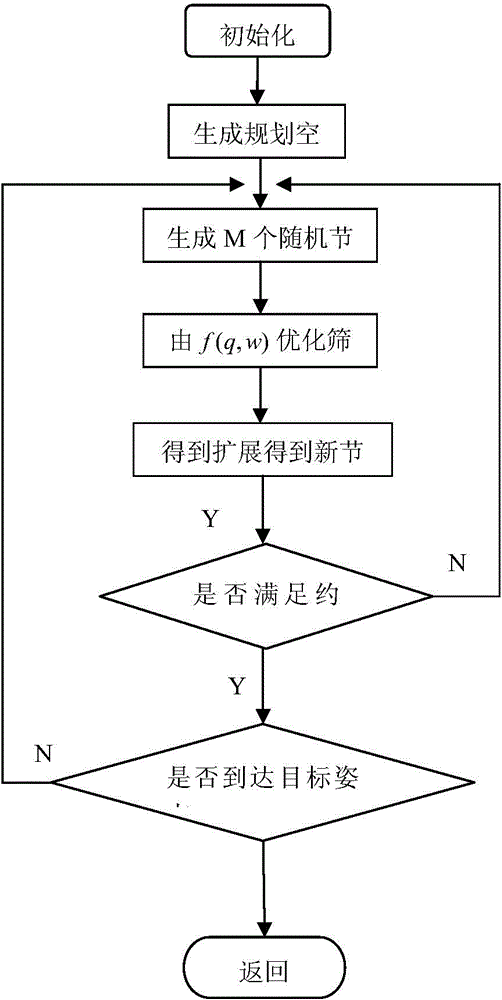
[0066] A kind of autonomous attitude maneuver control method of deep space probe disclosed in this example, the specific implementation steps are as follows:

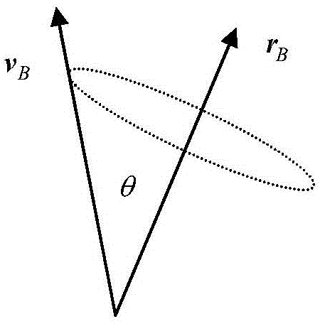
[0067] Step 1: Determine the vector of the sun in the inertial system as r according to the ephemeris time at the moment of attitude maneuver I =[1 0 0] T , and then determine the attitude transformation matrix from the inertial system to the detector body coordinate system as C BI = 0.4602 - 0.6354 0.6201 - 0.8786 - 0.4261 0.2156 0.1272 - 0.6440 ...


PUM


Abstract

The invention discloses an autonomous attitude maneuver control method of a deep space probe, which relates to the autonomous attitude maneuver control method and belongs to the technical field of spacecraft attitude control. The autonomous attitude maneuver control method comprises the following steps of carrying out random sampling on uniformly-distributed nodes of an attitude space with an ORRT (Optimized Rapidly Exploring Random Tree) algorithm as a path planning method, making a balance and choosing the optimum path to expand, carrying out incremental expansion in a safety space in a greedy expansion manner, respectively establishing a probe attitude maneuver dynamic constraint model, an actual engineering constraint model and a probe geometric constraint model under a probe body coordinate system to obtain path nodes which meet the constraint and generate a control moment for the nodes, thereby generating a probe attitude maneuver path and a required control moment, and implementing the purpose that probe maneuvers to a target attitude according to the generated probe attitude maneuver path and the required control moment. According to the autonomous attitude maneuver control method, the path planning time is shortened and the efficiency that the probe maneuvers to the target attitude from the initial attitude is improved under the condition that all kinds of complicated constraint conditions faced by the probe are met.

Description

technical field [0001] The invention relates to an autonomous attitude maneuver control method, which belongs to the technical field of spacecraft attitude control. Background technique [0002] During the operation of the detector in orbit, a large number of attitude maneuvers are required to complete the switching between different attitude orientations; at the same time, due to the diversity of detector tasks, there are certain spatial orientation constraints in the attitude maneuver process of some detectors. Second, the control inputs to the detectors are also constrained. This constraint is mainly caused by two factors: one is that the torque amplitude provided by the actuator is limited; the other is when the actuator is partially damaged. Third, due to the limited range of some angular velocity sensors, the angular velocity of the detector must be kept within a certain range, which forms an angular velocity constraint. Faced with the above constraints, the attitude...

Claims


Application Information

Patent Timeline
IPC IPC(8): G05D1/08
Inventor 徐瑞武长青崔平远朱圣英尚海滨
Owner BEIJING INSTITUTE OF TECHNOLOGYGY
Why Eureka
Try Eureka