Light-emitting display device

A technology of light-emitting display and light-emitting components, which is applied in the direction of instruments, electrical digital data processing, electrical components, etc., can solve the problems of poor optical efficiency and thickness of display devices, increase optical use efficiency, improve penetration, and reduce reflection The effect of the phenomenon

Active Publication Date: 2015-05-20
TRENDON TOUCH TECHNOLOGY CORPORATION
View PDF7 Cites 9 Cited by
  • Summary
  • Abstract
  • Description
  • Claims
  • Application Information

AI Technical Summary

Problems solved by technology

[0004] The object of the present invention is to provide a light-emitting display device, which has better image light utilization efficiency, and is lighter and thinn

Method used


Image

  • Light-emitting display device
  • Light-emitting display device
  • Light-emitting display device

Examples


no. 1 example

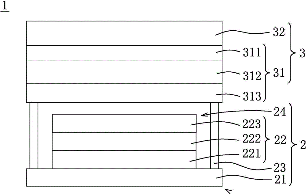
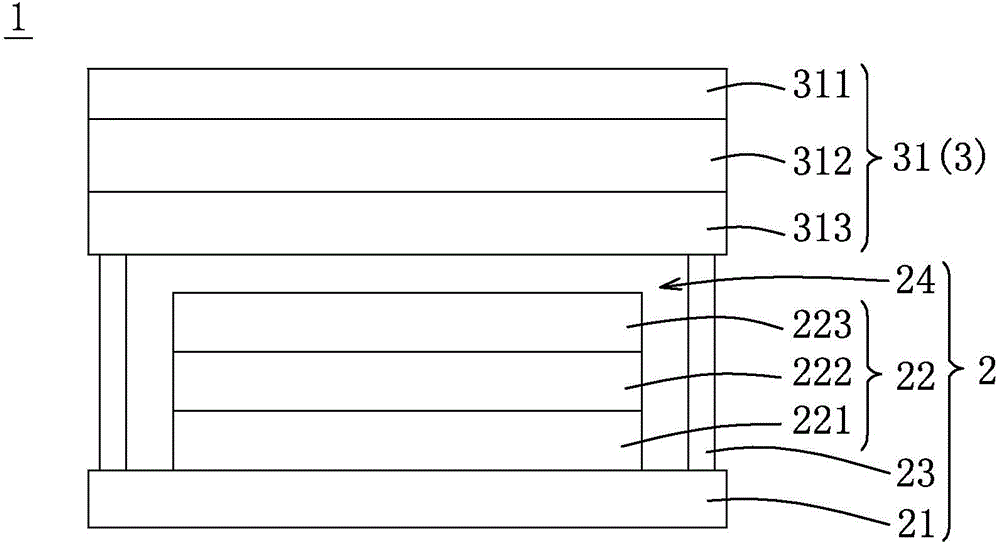
[0038] refer to figure 1 and figure 2 , is the first preferred embodiment of the light-emitting display device 1 of the present invention. As an application of an organic light emitting display, a light emitting display device 1 includes a light emitting component 2 and a packaging component 3 .

[0039]The light-emitting component 2 is used to provide image light for the light-emitting display device 1, which includes a substrate 21, a light-emitting structure 22 disposed on the substrate 21, and a sealing structure 23 disposed on the substrate 21 and surrounding the light-emitting structure 22, The space defined by the substrate 21 and the sealing structure 23 has an upper opening 24 . The light emitting structure 22 adopts an organic light emitting diode (OLED) as a display light source, and has a lower electrode layer 221 , a light emitting layer 222 and an upper electrode layer 223 sequentially arranged from bottom to top. The light-emitting layer 222 is the main ligh...

no. 2 example

[0055] refer to Figure 4 , Figure 5 , Image 6 , is the second preferred embodiment of the light-emitting display device 1 of the present invention. In the first preferred embodiment, the technical focus of the light-emitting display device 1 is that the light-emitting component 2 cooperates with the packaging component 3 having the brightening anti-reflection structure 31 , so its technical feature lies in the optical characteristics of the brightening anti-reflection structure 31 . In this embodiment, the packaging component 3 of the light-emitting display device 1 further includes a touch sensing structure 33 , so the light-emitting display device 1 of this embodiment belongs to a touch-sensitive display device.

[0056] In this embodiment, the touch sensing structure 33 has a first touch electrode layer 331, so the light-emitting display device 1 realizes the touch function with a single-layer touch electrode structure, and the first touch electrode layer 331 is made o...

no. 3 example

[0061] refer to Figure 8, is the third preferred embodiment of the light-emitting display device 1 of the present invention. In this embodiment, the packaging component 3 of the light-emitting display device 1 includes a brightening anti-reflection structure 31, a cover plate 32 and a touch sensing structure 33. The touch sensing structure 33 belongs to a single-layer touch electrode structure. However, compared with the second embodiment, the touch sensing structure 33 of this embodiment further includes a substrate 335, the substrate 335 is used for the first touch electrode layer 331 to be disposed thereon, and the first touch electrode layer 331 may adopt an electrode shape configuration similar to that of the second embodiment.

[0062] In this embodiment, the touch sensing structure 33 can be disposed between the cover plate 32 and the linear polarizing layer 311 (such as Figure 8 ), between the linear polarizing layer 311 and the reflective polarizing layer 312, bet...


PUM


Abstract

This invention provides a light-emitting display device that comprises a light-emitting part and a package part. The package part covers a top opening of the light-emitting part, and includes a brightening-antireflective structure. The brightening-antireflective structure has a linear polarizing layer, a quarter-wave plate and an antireflective layer. The linear polarizing layer is disposed apart from the light-emitting part. The linear polarizing layer permits a linear-polarized light with a first linear polarization direction passing through, and blocks a linear-polarized light with a second linear polarization direction. The quarter-wave plate is disposed adjacent to the light-emitting part. The quarter-wave plate coverts a linear-polarized light with the first linear polarization direction or a circularly-polarized light with a first circular polarization direction into one another, and converts a linear-polarized light with the second linear polarization direction or a circularly-polarized light with a second circular polarization direction into one another. The antireflection layer is disposed between the linear polarizing layer and the quarter-wave plate. The antireflection layer permits a linear-polarized light with the first linear polarization direction passing through, and reflects a linear-polarized light with the second linear polarization direction.

Description

technical field [0001] The invention relates to a light-emitting display device, in particular to a light-emitting display device provided with a reflective polarizing layer. Background technique [0002] The current organic light-emitting touch display device generally includes an organic light-emitting component, a packaging substrate, a touch sensing structure, an anti-reflection structure and a cover plate. The organic light emitting component provides a light source of the display device, and includes a plurality of organic light emitting diodes. The packaging substrate seals the organic light-emitting components inside, so as to prevent the organic light-emitting diodes from being damaged by components such as moisture and oxygen in the external environment. The touch sensing structure includes a structure of a substrate and a touch electrode to provide a touch sensing function. The anti-reflective structure includes multiple optical layers that slow the reflection o...

Claims


Application Information

Patent Timeline
IPC IPC(8): H01L27/32H01L51/52G06F3/041
Inventor 刘振宇龚立伟林熙乾卢宏傑
Owner TRENDON TOUCH TECHNOLOGY CORPORATION
Why Eureka
Try Eureka