Magnetic connector
A technology of magnetic connectors and magnetic components, applied in the direction of connection, parts of connection devices, contact parts, etc., can solve the problems of inconvenient processing, complex structure, difficult to move, etc., and achieve convenient processing, low processing cost, and convenient connection Effect
- Summary
- Abstract
- Description
- Claims
- Application Information
AI Technical Summary
Problems solved by technology
Method used
Image
Examples
Embodiment 1
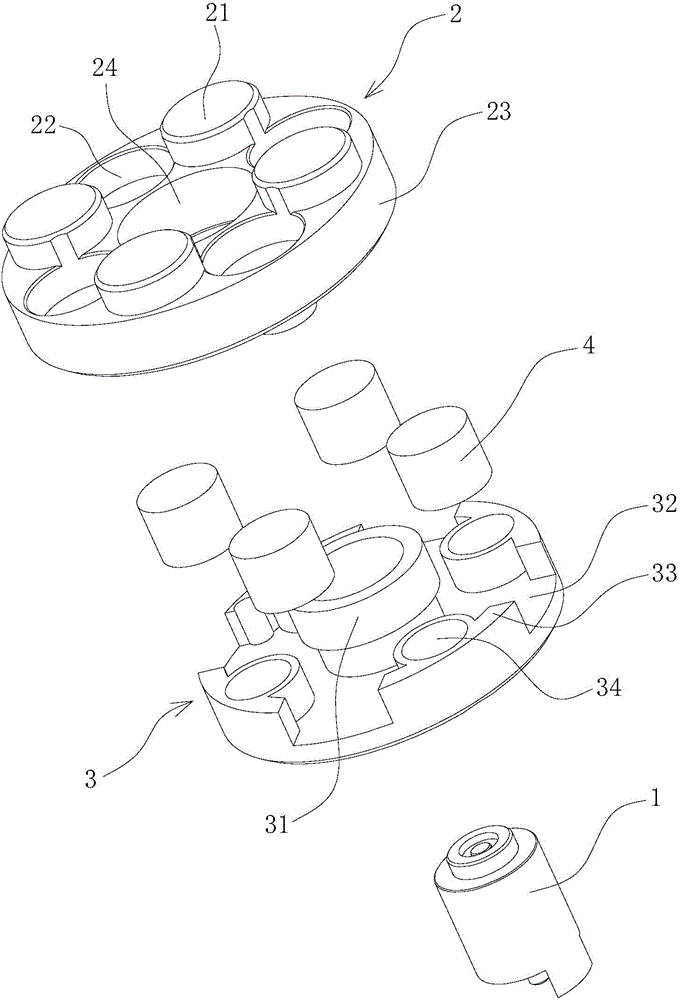
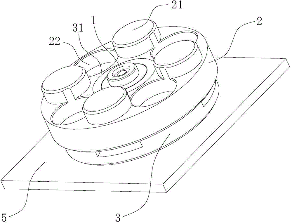
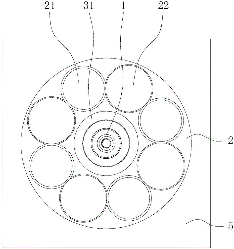
[0027] Figure 1 to Figure 5 A magnetic connector according to one embodiment of the present invention is schematically shown.
[0028] refer to Figure 1 ~ Figure 3 , The magnetic connector includes a concentric contact terminal 1, an insulating component 3 and a conductive magnetic component composed of a magnetically attractive metal end cap 2 and a magnet 4. The magnetic metal end cap 2 is fastened and fixedly connected with the insulating component 3 by clamping or threading. The concentric contact terminal 1 runs through the magnetic metal end cap 2 , and an insulating component 3 is provided between the concentric contact terminal 1 and the magnetic metal end cap 2 . The magnet 4 is located inside the magnetic metal end cap 2 , and can also be directly bonded or fixed outside the magnetic metal end cap 2 in other ways. The projected area of the magnet 4 on the cross-section of the magnetic metal end cap 2 is less than half of the cross-sectional area of the magne...
Embodiment 2
[0039] Figure 6 ~ Figure 7 A magnetic connector according to another embodiment of the present invention is schematically shown.
[0040] refer to Image 6 and Figure 7 , The magnetic connector includes a magnet 4, an end cap 5 and a bottom plate 6, and the magnetic connector is a cylindrical structure as a whole. The end cap 5 is engaged and fixedly connected with the bottom plate 6. The end cap 5 is provided with a protruding portion 51 and a through hole 52, and the protruding portion 51 and the through hole 52 are arranged at intervals. The shape of the protruding portion 51 matches the shape of the through hole 52. The protruding parts 51 and the through holes 52 can be correspondingly arranged in multiples and arranged in a rotationally symmetrical manner and correspond to mirror images. The interior of the protruding portion 51 is a hollow structure, the magnet 4 is located in the protruding portion 51 , and the bottom plate 6 is made of magnetically attractive met...
PUM
 Abstract
Description
Claims
Application Information
 - R&D
- Intellectual Property
- Life Sciences
- Materials
- Tech Scout
- Unparalleled Data Quality
- Higher Quality Content
- 60% Fewer Hallucinations
Browse by: Latest US Patents, China's latest patents, Technical Efficacy Thesaurus, Application Domain, Technology Topic, Popular Technical Reports.
© 2025 PatSnap. All rights reserved.Legal|Privacy policy|Modern Slavery Act Transparency Statement|Sitemap|About US| Contact US: help@patsnap.com


