
Motor assembly for lifting seat and vehicle seat containing motor assembly

A technology of motor components and seats, applied in the direction of electric components, electrical components, movable seats, etc., can solve the problems of high cost and complex structure, and achieve the effect of low cost, simple structure and convenient maintenance

Inactive Publication Date: 2015-05-20
上海胜华波汽车电器有限公司
View PDF6 Cites 33 Cited by
  • Summary
  • Abstract
  • Description
  • Claims
  • Application Information

AI Technical Summary

Problems solved by technology

[0005] One of the objectives of the present invention is to provide a motor assembly for raising the seat with a simple structure and low cost in view of the problems of complex structure and high cost in the existing vehicle seat reclining mechanism

Method used


Image

  • Motor assembly for lifting seat and vehicle seat containing motor assembly
  • Motor assembly for lifting seat and vehicle seat containing motor assembly
  • Motor assembly for lifting seat and vehicle seat containing motor assembly

Examples


Embodiment Construction

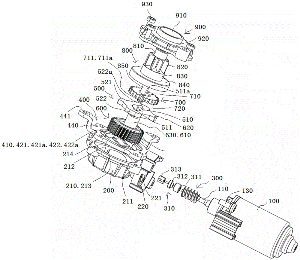
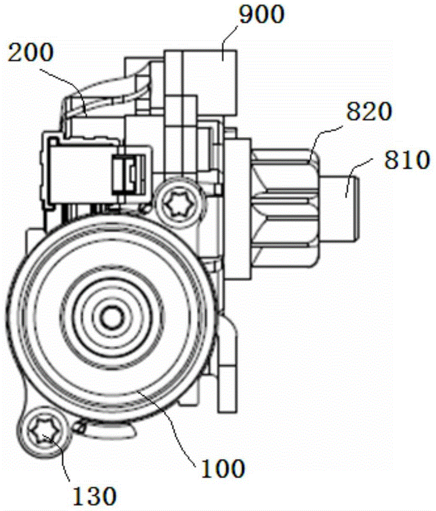
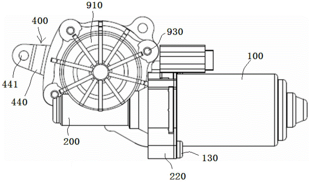
[0045] see Figure 1 to Figure 7 , the motor assembly of the raised seat shown in the figure includes a motor 100, a reduction box 200, a worm 300, a mounting bracket 400, a moving bracket 500, a double gear 600, a moving gear 700, an output gear assembly 800 and a reduction box cover 900.

[0046] The reduction box 200 is made of plastic and has an installation cavity 210 with an opening. The normal of the plane 211 where the opening is located is perpendicular to the axis of the output shaft 110 of the motor 100 . A motor mounting position 220 is provided on an outer surface of the reduction box body 200 , and an output shaft insertion hole 221 is disposed in the motor mounting position 220 , and the inner end of the output shaft insertion hole 221 communicates with the installation cavity 210 . The motor 100 is mounted on the motor mounting position 220 by using screws 130 , and the output shaft 110 of the motor 100 is inserted into the output shaft insertion hole 221 .

...


PUM


Abstract

The invention discloses a motor assembly for lifting a seat. The motor assembly comprises a motor, a reduction box body, a worm, a mounting bracket, a duplicate gear, a movable bracket, a mobile gear, an output gear assembly and a reduction box cover, wherein the reduction box cover is fixedly connected with the mounting bracket and the reduction box body, so as to enable the duplicate gear, the mobile gear, the movable bracket and a part, except for an output gear, of the output gear assembly to be sealed in an assembly chamber which is formed by the internal surface of the reduction box cover and the internal surfaces of the reduction box body; the motor drives a wormgear in the duplicate gear to rotate through the worm, the wormgear drives a movable bracket drive shaft, which is integrated with the wormgear, to eccentrically rotate, the movable bracket is driven to do up-and-down movement in a radial plane and drives the mobile gear to do elliptical-trajectory motion during up-and-down movement, the output gear assembly is driven to rotate through enabling the mobile gear to be engaged with an inner gear ring in the output gear assembly, the output gear engaged with a fan-shaped gear plate, and the fan-shaped gear plate is driven to rotate through engaged transmission so as to adjust the height of the seat.

Description

technical field [0001] The invention relates to the technical field of vehicle seats, in particular to a motor assembly for raising a seat and a vehicle seat including the motor assembly. Background technique [0002] Vehicle seats are sometimes configured to be adjustable to fit individual seated vehicle occupants according to their respective size and comfort criteria. For example, the vehicle seat back may be configured to tilt fore and aft relative to the seat cushion assembly, and / or the entire vehicle seat may be configured to move fore and aft relative to the floor of the vehicle. Portions of the seat may be configured to be adjusted simultaneously by the occupant or independently. [0003] In US Pat. No. 7,458,294, a spindle or worm drive is described for use in an adjusting device for a motor vehicle fastened to a first of two parts with a fixed spindle or fixed rack and provided with a connection to The gear mechanism of the second of the two components. The sup...

Claims


Application Information

Patent Timeline
Patent Type & Authority Applications(China)
IPC IPC(8): H02K7/116B60N2/22F16H1/20
CPCH02K7/116B60N2/22F16H1/203
Inventor 王特王丽慧王佳佳宋宇
Owner 上海胜华波汽车电器有限公司
Learn More