
Permanent magnet synchronous motor vector control speed regulating method based on MEMS (micro electro mechanical system) gyro

A technology of permanent magnet synchronous motor and vector control, which is applied in the direction of vector control system, motor generator control, electronic commutation motor control, etc. Problems such as information lag, to overcome the effect of low resolution

Inactive Publication Date: 2015-05-20
NORTHWESTERN POLYTECHNICAL UNIV
View PDF2 Cites 1 Cited by
  • Summary
  • Abstract
  • Description
  • Claims
  • Application Information

AI Technical Summary

Problems solved by technology

There is a certain lag in the speed feedback information, and the accuracy at low speeds is poor
The harsh working environment makes digital encoders and potentiometers prone to failure and reduces the performance of the speed control system
The position sensorless control technology is a design idea that gets rid of the hardware, but the filtering in the current and voltage acquisition process will cause the position information to lag behind and the accuracy is poor

Method used


Image

  • Permanent magnet synchronous motor vector control speed regulating method based on MEMS (micro electro mechanical system) gyro

Examples


Embodiment Construction

[0019] The present invention will be further described below in conjunction with the accompanying drawings and embodiments.

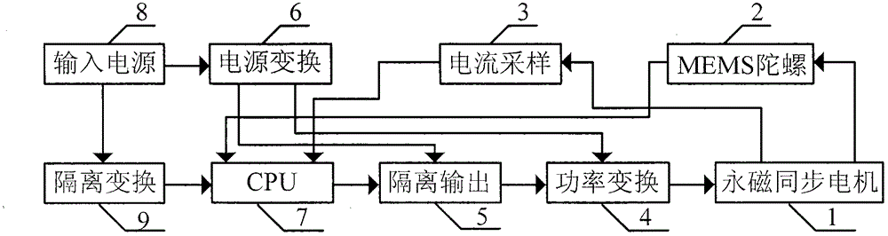
[0020] The structural reference of embodiment example of the present invention figure 1 , consists of permanent magnet synchronous motor 1, MEMS gyro 2, current sampling 3, power conversion 4, isolated output 5, power conversion 6, CPU 7, input power 8, isolation conversion 9.

[0021] The main performance of the permanent magnet synchronous motor 1 is as follows: brushless, rated current 2.1A, rated voltage 27V, rated speed 1800rpm, operating temperature -40°C ~ +80°C, the magnetic steel of the motor design is neodymium iron stilt, and the iron core material is DW360 .

[0022] MEMS gyro 2 adopts L3G4200D provided by ST Company as a three-axis digital gyroscope. The main features are as follows: digital communication interface supports I 2 C and SPI, the configurable range is ±250 / 500 / 2000dps.

[0023] Current sampling 3 uses Hall current sensor ACS...


PUM


Abstract

The invention discloses a permanent magnet synchronous motor vector control speed regulating method based on an MEMS (micro electro mechanical system) gyro. The MEMS gyro is used for providing rotor position information required by permanent magnet synchronous motor vector control speed regulation. In speed loop control, the output of the MEMS gyro is read and is used as speed loop feedback, and the output of a speed loop is generated by combining the speed loop giving and adopting a control method. In the current loop control, the output of the MEMS gyro is integrated by combining the time interval of each control period, and the rotor position information is obtained. The current loop output is generated by combining the rotor position information, the speed loop output, phase current signals and the control method. According to an initial position obtaining method during the MEMS gyro output integration, an A phase upper bridge and B and C phase lower bridges are conducted, a stator winding coincident with an axial line of an A phase winding is formed, and a d axle of a two-phase rotating coordinate system is attracted to the axial line of the A phase winding. The moment is used as a zero-degree position of the angle during the control.

Description

technical field [0001] The invention relates to a method for vector control and speed regulation of a permanent magnet synchronous motor based on a MEMS gyroscope. Background technique [0002] Permanent magnet synchronous motors use permanent magnets to generate air-gap flux without external excitation. They have excellent efficiency characteristics, high power density, and torque-to-inertia ratio, making them the first choice for servo control systems. Vector control takes the rotor flux vector as the reference coordinate, divides the stator current into the excitation component and the torque component for independent control, and has good anti-disturbance performance no matter in the low-speed operation area of ​​the motor or in the high-speed operation area of ​​the motor. Start-up braking performance And stable performance, widely used in permanent magnet synchronous motor speed control system. On the one hand, the position sensor provides angle information for vector...

Claims


Application Information

Patent Timeline
IPC IPC(8): H02P21/00
Inventor 王德成周经伟林辉
Owner NORTHWESTERN POLYTECHNICAL UNIV
Features
  • Generate Ideas
  • Intellectual Property
  • Life Sciences
  • Materials
  • Tech Scout
  • Unparalleled Data Quality
  • Higher Quality Content
  • 60% Fewer Hallucinations
Learn More