
Multi-frequency ultrasonic observation method, device and equipment

A multi-frequency ultrasound and observation device technology, which is applied in ultrasound/sonic/infrasonic diagnosis, ultrasound/sonic/infrasonic Permian technology, and acoustic diagnosis, can solve the problems of shallow detection depth and low resolution, and improve imaging efficiency, overcoming the effect of lower resolution

Active Publication Date: 2018-11-20
SUZHOU INST OF BIOMEDICAL ENG & TECH CHINESE ACADEMY OF SCI
View PDF6 Cites 2 Cited by
  • Summary
  • Abstract
  • Description
  • Claims
  • Application Information

AI Technical Summary

Problems solved by technology

[0005] In view of this, the embodiment of the present invention provides a multi-frequency ultrasonic observation method, device and equipment to solve the problems of low resolution or shallow detection depth existing in the form of using the same image to represent the same tissue position

Method used


Image

  • Multi-frequency ultrasonic observation method, device and equipment
  • Multi-frequency ultrasonic observation method, device and equipment
  • Multi-frequency ultrasonic observation method, device and equipment

Examples


Embodiment 1

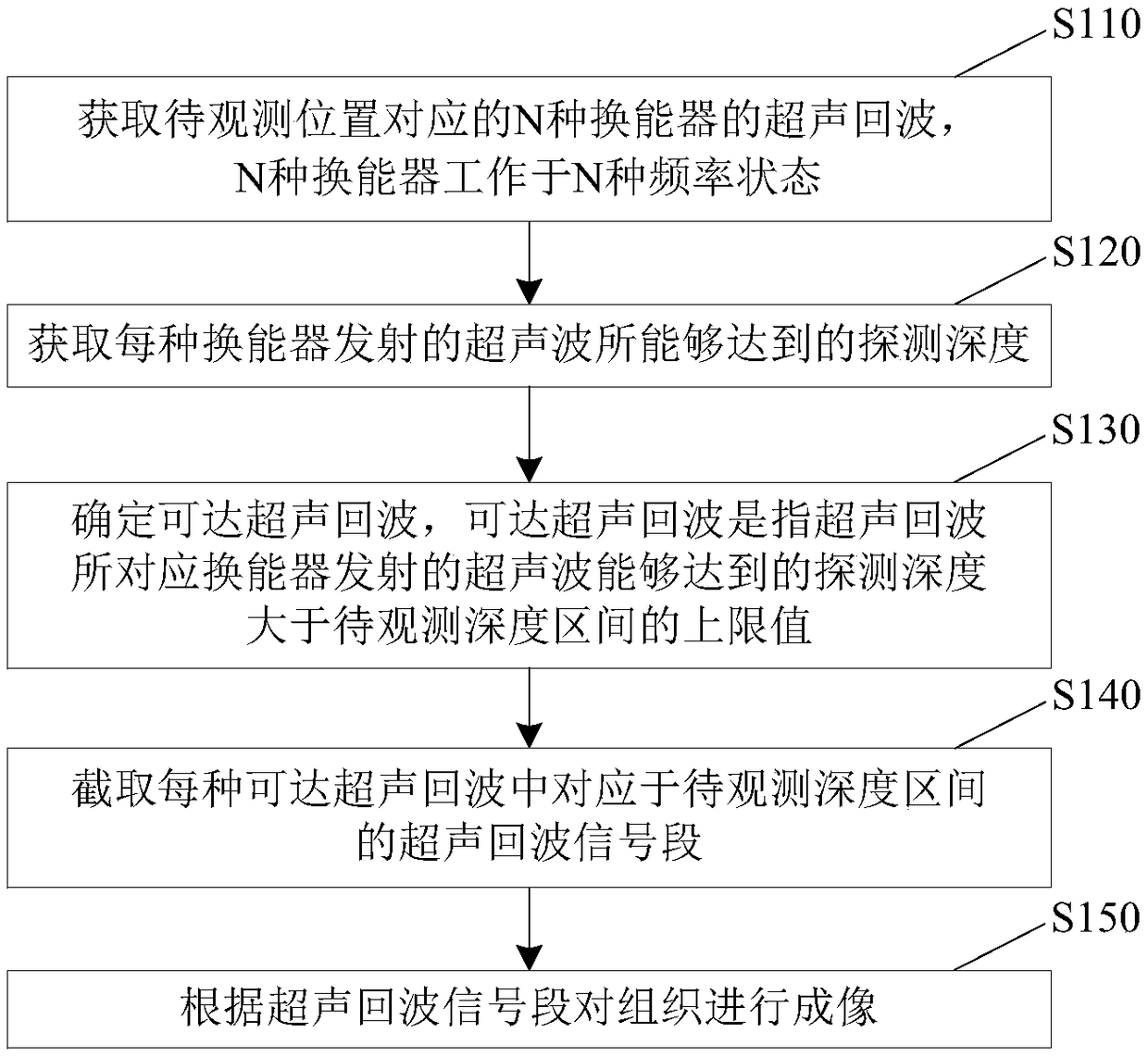
[0026] figure 1 A flow chart of a multi-frequency ultrasonic observation method according to an embodiment of the present invention is shown. Such as figure 1 As shown, the method includes the following steps:

[0027] S110: Obtain ultrasonic echoes of N types of transducers corresponding to the position to be observed, where N types of transducers work in N types of frequency states, and N is a natural number greater than or equal to 2.

[0028] The N kinds of frequency states in this step refer to the N kinds of center frequencies, the upper limit of the frequency interval, the lower limit of the frequency interval, or a combination of any two of the three. For example, the center frequencies of the N types of transducers are different. Such as figure 2 As shown, three kinds of transducers 1, 2, and 3 are used to emit ultrasonic waves and receive ultrasonic echoes at the position to be observed, and these three kinds of transducers are low-frequency, intermediate-freque...

Embodiment 2

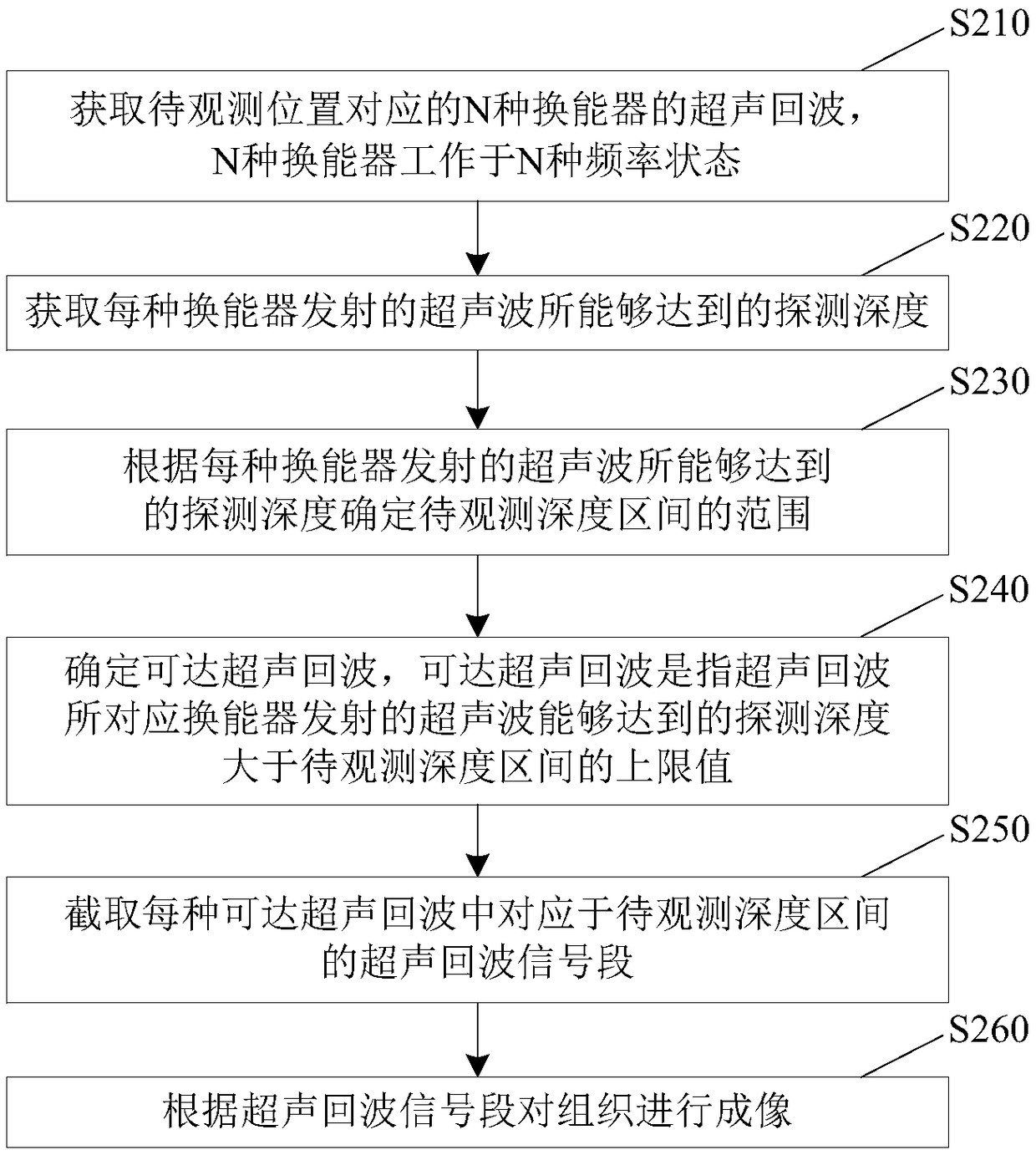
[0042] image 3 A flow chart of a multi-frequency ultrasonic observation method according to an embodiment of the present invention is shown. Such as image 3 As shown, the method includes the following steps:

[0043] S210: Obtain ultrasonic echoes of N types of transducers corresponding to the position to be observed, where N types of transducers work in N types of frequency states, and N is a natural number greater than or equal to 2. Please refer to step S110.

[0044] S220: Obtain the detection depth that can be reached by the ultrasonic waves emitted by each transducer.

[0045] The step of obtaining may be to obtain the first time T1 when the transducer emits ultrasonic waves first, obtain the second time T2 when the transducer finally receives the ultrasonic echo, and then calculate the detection depth h= v*(T2-T1) / 2, where v is the propagation speed of ultrasound in the tissue.

[0046] Ultrasonic waves emitted by the transducer will form ultrasonic echoes due to...

Embodiment 3

[0055] Figure 4 A functional block diagram of a multi-frequency ultrasonic observation device according to an embodiment of the present invention is shown. The multi-frequency ultrasonic observation device can be used to implement the multi-frequency ultrasonic observation method described in Embodiment 1 or Embodiment 2. Such as Figure 4 As shown, the device includes a first acquisition unit 10 , a second acquisition unit 20 , a first determination unit 30 , an interception unit 40 and an imaging unit 50 .

[0056] The first acquiring unit 10 is used to acquire ultrasonic echoes of N types of transducers corresponding to the position to be observed, the N types of transducers work in N types of frequency states, and N is a natural number greater than or equal to 2. The second acquiring unit 20 is configured to acquire the detection depth that can be reached by the ultrasonic waves emitted by each transducer. The first determining unit 30 is used to determine the reachabl...


PUM


Abstract

The invention discloses a multi-frequency ultrasonic observation method, device and equipment. The method comprises the following steps: acquiring ultrasonic echoes of N energy converters corresponding to a to-be-observed location, wherein the N energy converters are worked at N frequency states; acquiring the reachable detection depth of the ultrasonic wave emitted by each energy converter; determining the reachable ultrasonic echo, wherein the reachable ultrasonic echo means that the reachable detection depth of the ultrasonic wave emitted by the energy converter corresponding to the ultrasonic echo is greater than an upper limit value of the to-be-observed depth interval; intercepting an ultrasonic echo signal segment corresponding to the to-be-observed depth interval in each reachableultrasonic echo; performing imaging in the organization according to the ultrasonic echo signal segment. The deep detection depth can be achieved through the energy converter with low frequency, and the resolution in the shallow depth range can be improved through the energy converter with high frequency, the problem that the resolution is low or the detection depth is shallow is overcome, and theimaging efficiency is improved.

Description

technical field [0001] The invention relates to the technical field of ultrasonic imaging, in particular to a multi-frequency ultrasonic observation method, device and equipment. Background technique [0002] Ultrasound imaging technology uses the reflected and scattered echoes generated by ultrasonic waves in tissues to form images for the identification and diagnosis of diseases. Therefore, the steps of ultrasonic imaging are to firstly control the ultrasonic transducer to emit ultrasonic waves toward the tissue and receive ultrasonic echoes, and then perform imaging according to the ultrasonic echoes. [0003] Existing ultrasonic imaging methods often use probes integrated with low-frequency, intermediate-frequency or high-frequency transducers to obtain ultrasonic echo signals, and obtain ultrasonic images based on these, displaying all information within the reachable depth range of ultrasound in the same image. [0004] However, when the ultrasonic frequency emitted b...

Claims


Application Information

Patent Timeline
IPC IPC(8): A61B8/00
CPCA61B8/145A61B8/4483A61B8/48
Inventor 焦阳李章剑沈之天崔崤峣杨晨吕加兵
Owner SUZHOU INST OF BIOMEDICAL ENG & TECH CHINESE ACADEMY OF SCI
Features
  • Generate Ideas
  • Intellectual Property
  • Life Sciences
  • Materials
  • Tech Scout
  • Unparalleled Data Quality
  • Higher Quality Content
  • 60% Fewer Hallucinations
Learn More