Touch control press key structure, electronic equipment and manufacturing method of touch control press key structure

A manufacturing method and button technology, applied to the touch button structure, touch button structure manufacturing, and electronic equipment fields, can solve the problems of increasing the thickness of mobile phones and achieve good insulation effects

Active Publication Date: 2015-05-20
GUANGDONG OPPO MOBILE TELECOMM CORP LTD
8 Cites 3 Cited by

AI-Extracted Technical Summary

Problems solved by technology

However, this structure has a thicker thickness, which leads to an increase in the thickness of...

Method used

The button ink layer 12 and the first decorative ink layer 13 are covered on the surface of the cover glass 11, specifically, the button ink layer 12 and the first decorative ink layer 13 are covered on the inside of the cover glass 11 surface. The first decorative ink layer 13 is used to decorate the cover glass 11 and cover the electronic components and circuits arranged inside the cover glass 11 , so that the user can observe a good appearance when using the electronic device 20 .
[0038] Referring to FIG. 1 and FIG. 2, the first embodiment of the present invention provides a touch key structure 10. The touch button structure 10 of the present invention can be installed in various mobile electronic devices that need to realize the touch function, such as mobile phones and tablet computers. In this embodiment, the touch key structure 10 is arranged on the electronic device 20 , so as to be convenient for realizing the required touch operation through the touch electronic device 20 .
[0043] The first insulating ink layer 15 covers the first decorative ink layer 13 and the button ink layer 12, and the silver paste layer 17 is formed on the surface of the first insulating ink layer 15. The first insulating ink layer 15 is used to prevent the key ink layer 12 from interfering with the touch performance of the silver paste layer 17 .
[0045] The second insulating ink layer 19 covers the silver paste layer 17, thereby preventing other components of the silver paste layer 17 electronic equipment 20 from infecting the touch performance of the touch key structure 10. At the same time, the first insulating ink layer 15 and the second insulating ink layer 19 protect the silver paste layer 17 . Further, the second insulating ink layer 19 can cover the surface of the silver paste layer 17, and can further coat the side of the silver paste layer 17, so as to achieve a good insulation effect.
[0057] Step S106, setting the second insulating ink layer 19 on the silver paste layer 17. In this step, the second insulating ink layer 19 is used to form insulating protection for the silver paste layer 17 . Further, the second insulating ink layer 19 can cover...

Abstract

The invention provides a touch control press key structure, which comprises cover plate glass, a press key ink layer, a first decoration ink layer, a first insulation ink layer, a silver paste layer and a second insulation ink layer, wherein the press key ink layer and the first decoration ink layer are formed on the surface of the cover plate glass, the first insulation ink layer is arranged above the press key ink layer and the first decoration ink layer, the silver paste layer is arranged on the first insulation ink layer, the second insulation ink layer covers the silver paste layer, the silver paste layer is provided with a silver paste line, and the silver paste line corresponds to the press key ink layer to form a touch control region. The touch control press key structure completes the touch control operation under the condition with the thinner thickness. In addition, the first insulation ink layer and the second insulation ink layer cover the silver paste layer, so that the good insulation effect is realized. The invention also provides a manufacturing method of the touch control press key structure.

Application Domain

Technology Topic

Image

  • Touch control press key structure, electronic equipment and manufacturing method of touch control press key structure
  • Touch control press key structure, electronic equipment and manufacturing method of touch control press key structure
  • Touch control press key structure, electronic equipment and manufacturing method of touch control press key structure

Examples

  • Experimental program(1)

Example Embodiment

[0037] The technical solutions in the embodiments of the present invention will be clearly and completely described below in conjunction with the accompanying drawings in the embodiments of the present invention. Obviously, the described embodiments are only a part of the embodiments of the present invention, rather than all the embodiments. Based on the embodiments of the present invention, all other embodiments obtained by those of ordinary skill in the art without creative work shall fall within the protection scope of the present invention.
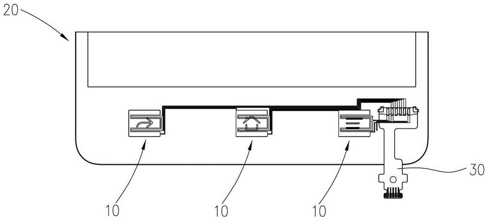
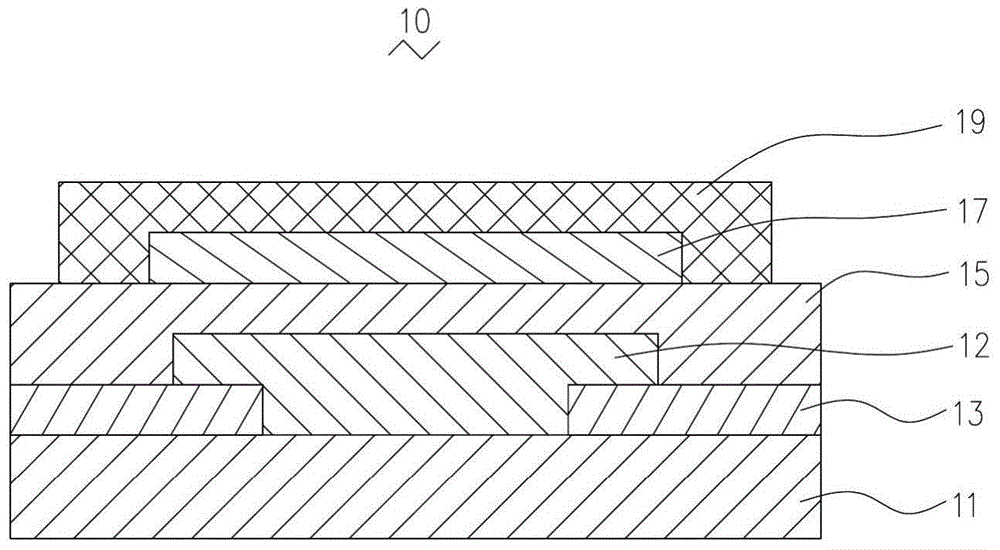
[0038] See figure 1 and figure 2 The first embodiment of the present invention provides a touch key structure 10. The touch button structure 10 of the present invention can be installed in various mobile electronic devices that need to implement touch functions, such as mobile phones and tablet computers. In this embodiment, the touch button structure 10 is disposed on the electronic device 20, so as to facilitate the use of the touch control electronic device 20 to realize the required touch operation.
[0039] The touch key structure 10 includes a cover glass 11, a key ink layer 12, a first decorative ink layer 13, a first insulating ink layer 15, a silver paste layer 17, and a second insulating ink layer 19. The silver paste layer 17 is connected to a control circuit (not shown) through a flexible circuit board 30 provided by the electronic device 20, so as to perform a touch operation.
[0040] The button ink layer 12 and the first decorative ink layer 13 cover the surface of the cover glass 11. Specifically, the button ink layer 12 and the first decorative ink layer 13 cover the inner surface of the cover glass 11. The first decorative ink layer 13 is used to decorate the cover glass 11 and shield the electronic components and circuits arranged inside the cover glass 11, so that the user can see a good appearance when using the electronic device 20 .
[0041] The key ink layer 12 is used to identify the touch sensing area of ​​the touch key, so as to facilitate instructing the user to press the corresponding area to perform a touch operation.
[0042] In this embodiment, the first decorative ink layer 13 and the button ink layer 12 adopt different colors. Preferably, the first decorative ink layer 13 is white or black. When the first decorative ink layer 13 is white, the thickness of the first decorative ink layer 13 is less than 0.04 mm. When the first decorative ink layer 13 is black, the thickness of the first decorative ink layer 13 is less than 0.02 mm.
[0043] The first insulating ink layer 15 covers the first decorative ink layer 13 and the key ink layer 12, and the silver paste layer 17 is formed on the surface of the first insulating ink layer 15. The first insulating ink layer 15 is used to prevent the key ink layer 12 from interfering with the touch performance of the silver paste layer 17.
[0044] The silver paste layer 17 includes silver paste lines for connecting the flexible circuit board 30, and the silver paste lines of the silver paste layer 17 form a touch area corresponding to the key ink layer 12, thereby sensing the user's touch operation . It is understandable that the touch area provided by the silver paste layer 17 can adopt applicable existing technology, for example, the silver paste layer 17 can be provided by a self-capacitive technology, so as to realize the touch operation of the user.
[0045] The second insulating ink layer 19 covers the silver paste layer 17, so as to prevent the silver paste layer 17 from infecting the touch performance of the touch key structure 10 by other components of the electronic device 20. At the same time, the first insulating ink layer 15 and the second insulating ink layer 19 protect the silver paste layer 17. Furthermore, the second insulating ink layer 19 can cover the surface of the silver paste layer 17, and can further cover the side surface of the silver paste layer 17, so as to achieve a good insulation effect.
[0046] See image 3 , The manufacturing method of the touch key structure 10 in this embodiment includes the following steps:
[0047] In step S101, a cover glass 11 is provided. It is understandable that the cover glass 11 can be used as a panel of an electronic device, such as a mobile phone, and the user can touch the outer surface of the cover glass 11 to complete the touch operation of the mobile phone.
[0048] In step S101, the following steps may be further included:
[0049] Step S1011, providing a glass substrate and cutting the glass substrate to a required size, so as to obtain the cover glass 11;
[0050] Step S1012, cleaning the cover glass 11;
[0051] Step S1013, drying the cover glass 11.
[0052] Through the above steps, a cover glass 11 suitable for electronic devices can be obtained, so that various functional layers can be arranged on the cover glass 11. It can be understood that the size of the cover glass 11 can be set according to the size of the corresponding electronic device.
[0053] In step S102, a first decorative ink layer 13 is provided, and the first decorative ink layer 13 is hollowed out to form a button area. The first decorative ink layer 13 can be disposed on the cover glass 11 by printing. It is understandable that the first decorative ink layer 13 can also be formed on the cover glass 11 in other suitable ways.
[0054] In step S103, a key ink layer 12 is provided on the cover glass 11 of the key area of ​​the first decorative ink layer 13. The key ink layer 12 can be disposed on the cover glass 11 of the key area of ​​the first decorative ink layer 13 by printing. It is understandable that the key ink layer 12 can also be formed on the cover glass 11 of the key area of ​​the first decorative ink layer 13 in other suitable ways.
[0055] In step S104, a first insulating ink layer 15 is provided on the first decorative ink layer 13 and the button ink layer 12. The first insulating ink layer 15 can be disposed on the first decorative ink layer 13 and the button ink layer 12 by printing. It is understandable that the first insulating ink layer 15 can also be formed on the first decorative ink layer 13 and the key ink layer 12 in other suitable ways.
[0056] In step S105, a silver paste layer 17 is provided on the first insulating ink layer 15. In this step, the silver paste layer 17 is printed to realize the touch function of the touch key structure 10. The silver paste layer 17 can be disposed on the first insulating ink layer 15 by printing. It is understandable that the silver paste layer 17 can also be formed on the first insulating ink layer 15 in other suitable ways.
[0057] Step S106, disposing a second insulating ink layer 19 on the silver paste layer 17. In this step, the second insulating ink layer 19 is used to form insulation protection for the silver paste layer 17. Furthermore, the second insulating ink layer 19 can cover the surface of the silver paste layer 17, and can further cover the side surface of the silver paste layer 17, so as to achieve a good insulation effect. The silver paste layer 17 can be disposed on the first insulating ink layer 15 by printing. It is understandable that the silver paste layer 17 can also be formed on the first insulating ink layer 15 in other suitable ways.
[0058] See Figure 4 The second embodiment of the present invention provides a touch key structure 40. The touch key structure 40 in this embodiment is substantially the same as the first embodiment, and includes a cover glass 41, a first decorative ink layer 43, and key ink Layer 42, first insulating ink layer 45, silver paste layer 47, and second insulating ink layer 49. The first decorative ink layer 43 and the key ink layer 42 are formed on the surface of the cover glass 41.
[0059] The difference is that, in this embodiment, the touch button structure 40 is further provided with a second decorative ink layer 44. The second decoration ink layer 44 is formed on the first decoration ink layer 43 and the key ink layer 42 and covers the first decoration ink layer 43 and the key ink layer 42. The second decorative ink layer 44 is used to ensure complete coverage of the cover glass 41 by the ink layer and sufficient concealment to ensure the appearance of the cover glass 41. At the same time, the second decorative ink layer 44 can form a flat surface on the first decorative ink layer 43 and the button ink layer 42, which can ensure the flatness after covering, thereby facilitating the installation of the first insulating ink layer 45 and ensuring the The first insulating ink layer 45 has a good insulating effect. The first insulating ink layer 45, the silver paste layer 47, and the second insulating ink layer 49 are stacked on the second decorative ink layer 44 on one side.
[0060] See Figure 5 , The manufacturing method of the touch button structure 40 in this embodiment includes the following steps:
[0061] In step S201, a cover glass 41 is provided.
[0062] In step S202, a first decorative ink layer 43 is provided, and the first decorative ink layer 43 is hollowed out to form a button area.
[0063] In step S203, a key ink layer 42 is provided on the cover glass 41 of the key area of ​​the first decorative ink layer 43.
[0064] In step S204, a second decorative ink layer 44 is provided on the first decorative ink layer 43 and the button ink layer 42. The second decorative ink layer 44 can be disposed on the first decorative ink layer 43 and the button ink layer 42 by printing. It is understandable that the second decorative ink layer 44 can also be formed on the first decorative ink layer 43 and the key ink layer 42 in other suitable ways.
[0065] In step S205, a first insulating ink layer 45 is provided on the second decorative ink layer 44 and the button ink layer 42.
[0066] In step S206, a silver paste layer 47 is disposed on the first insulating ink layer 45.
[0067] In step S207, a second insulating ink layer 49 is provided on the silver paste layer 47.
[0068] The present invention also provides an electronic device that adopts the touch key structure 10, 40 as described above.
[0069] The touch button structure 10 of the present invention and the electronic device adopting the touch button structure 10 adopt a silver paste layer 17 formed on the cover glass 11, and connected to the flexible circuit board 30, and then connected to the control circuit, so as to realize the touch function . Since the thickness of the silver paste layer 17 is relatively thin, the electronic device 20 can complete the touch operation under the condition of a relatively thin thickness. Moreover, the touch button structure 10 of the present invention and the electronic device 20 adopting the touch button structure 10 are covered with the silver paste layer 17 by providing a first insulating ink layer 15 and a second insulating ink layer 19, thereby achieving good Insulation effect.
[0070] What is disclosed above is only one embodiment of the present invention. Of course, it cannot be used to limit the scope of rights of the present invention. A person of ordinary skill in the art can understand all or part of the procedures for implementing the above embodiments and make them in accordance with the claims of the present invention. The equivalent changes still fall within the scope of the invention.

PUM

PropertyMeasurementUnit
Thickness<= 0.04mm
Thickness<= 0.02mm
tensileMPa
Particle sizePa
strength10

Description & Claims & Application Information

We can also present the details of the Description, Claims and Application information to help users get a comprehensive understanding of the technical details of the patent, such as background art, summary of invention, brief description of drawings, description of embodiments, and other original content. On the other hand, users can also determine the specific scope of protection of the technology through the list of claims; as well as understand the changes in the life cycle of the technology with the presentation of the patent timeline. Login to view more.

Similar technology patents

Classification and recommendation of technical efficacy words

Why Eureka
Try Eureka