
Automatic irrigator with humidity detecting device

A humidity detection device and automatic irrigation technology, applied in watering devices, gardening, botanical equipment and methods, etc., can solve the problems of unable to detect soil humidity in real time, only timing, etc., and achieve the goal of improving irrigation efficiency and intelligence Effect

Inactive Publication Date: 2015-05-27
西安思创达通讯科技有限责任公司
View PDF0 Cites 2 Cited by
  • Summary
  • Abstract
  • Description
  • Claims
  • Application Information

AI Technical Summary

Problems solved by technology

[0008] The purpose of the present invention is to overcome the problem that soil moisture cannot be detected in real time in the prior art, so that irrigation can only be done regularly and quantitatively, and it is difficult to formulate the optimal irrigation strategy according to the current soil moisture

Method used


Image

  • Automatic irrigator with humidity detecting device

Examples


Embodiment 1

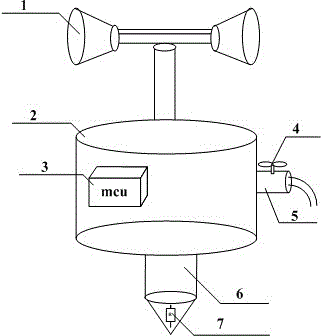
[0016] An automatic irrigator with a humidity detection device, including a nozzle, a casing, a controller, a solenoid valve, a water inlet, a detection rod, and a hygrometer, and is characterized in that: the nozzle is installed on the upper part of the casing; the controller is installed on the left side of the casing position; the water inlet is connected to the right side of the casing; the solenoid valve is installed at the front of the water inlet; the detection rod is embedded in the lower part of the casing; the humidity sensitive resistor is installed inside the detection rod.

[0017] The invention solves the problem that the general automatic irrigation device can only irrigate regularly and quantitatively, but cannot form effective feedback by detecting soil humidity. By detecting soil moisture in real time, the most effective irrigation is performed at the optimum moisture point.

Embodiment 2

[0019] The casing of the present invention adopts a cylindrical shape, the detection rod adopts a conical and cylindrical shape, and the nozzle is in the shape of a truncated cone. Such design makes the present invention close to the current existing irrigation appliances to the greatest extent. On the one hand, it is easy to be accepted by people psychologically, and on the other hand, the existing parts can be fully utilized, which effectively reduces the cost.

[0020] In actual use, when the detection rod of the present invention is inserted into the soil, the controller starts to control the humidity sampling through the humidity sensitive resistor and calculates continuously. When the humidity value reaches the specified value, the controller controls the solenoid valve to open, and the water flows through The water inlet enters the nozzle, and then sprays out from the nozzle to reach the root system of the crop.

[0021] In this way, our irrigation is based on actual s...


PUM


Abstract

The invention belongs to the technical field of electronic information and agricultural irrigation and specifically provides an automatic irrigator with a humidity detecting device. The automatic irrigator comprises a spray head, an outer housing, a controller, a solenoid valve, a water inlet, a detecting rod and a humidity sensitive resistor. The automatic irrigator is characterized in that the controller is mounted on the left position inside the housing, wherein the water inlet is connected to the right side of the housing; the solenoid valve is mounted at the front end of the water inlet; the detecting rod is embedded to the lower part of the housing; the humidity sensitive resistor is mounted inside the detecting rod. The automatic irrigator solves the problems that an existing automatic irrigating device only can perform timing irrigation, and cannot detect soil humidity and irrigate the best water amount at the best time. By detecting the soil humidity, the efficiency is improved and the water consumption is reduced.

Description

technical field [0001] The invention belongs to the technical field of electronic information and agricultural irrigation, and in particular relates to an automatic irrigator with a humidity detection device. Background technique [0002] The current social and economic development is getting faster and faster, and at the same time, the consumption of resources is becoming more and more intense. As the pillar of industry and service industry, the automation and energy saving of agricultural production has become an urgent problem to be solved. [0003] At present, flood irrigation is still used in most areas of our country, which not only wastes water resources, but also has low irrigation efficiency. [0004] On this basis, sprinkler irrigation, drip irrigation and other methods have been promoted in some areas, but many of these devices still only take advantage of the water-saving characteristics of the nozzle and the long-distance characteristics of high water pressure ...

Claims


Application Information

Patent Timeline
Patent Type & Authority Applications(China)
IPC IPC(8): A01G25/16
CPCA01G25/167A01G25/02
Inventor 巨杰
Owner 西安思创达通讯科技有限责任公司
Learn More