Eureka AIR delivers breakthrough ideas for toughest innovation challenges, trusted by R&D personnel around the world.

Shredder with pull rod

A paper shredder and pull rod technology, which is applied in the direction of grain processing, etc., can solve the problem of inconvenient handling of the paper shredder, and achieve the effect of simple structure and energy saving

Inactive Publication Date: 2015-05-27
SHAANXI BOYUAN SCI & TECH DEV
View PDF0 Cites 0 Cited by
  • Summary
  • Abstract
  • Description
  • Claims
  • Application Information

AI Technical Summary

Problems solved by technology

[0003] The technical problem to be solved by the present invention is to solve the defect that the existing paper shredders are inconvenient to carry

Method used


Image

  • Shredder with pull rod
  • Shredder with pull rod

Examples


Embodiment Construction

[0013] In order to overcome the defect that the existing paper shredders are inconvenient to carry, a rod shredder will be further described in detail below with reference to the drawings and embodiments.

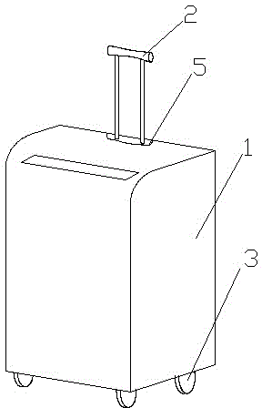
[0014] Such as Figure 1-2 The shown rod shredder includes a casing 1 , a pull rod 2 is arranged on the back of the casing 1 , and a running device 3 is arranged on the bottom surface of the casing 1 . It can be seen that in the process of transporting, the shredder can be transported by pulling the pull rod 2, which has a simple structure and is convenient for transporting.

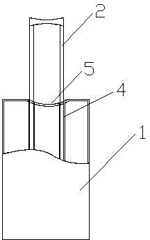
[0015] Wherein, for the said pull rod, it does not affect the overall structure of the paper shredder, and it can be picked up and carried when encountering obstacles such as stairs, and the pull rod 2 does not affect the use of the paper shredder when placed at the same time, so the said shell The inner side of the back of the body 1 is provided with a track 4, the pull rod 2 is slidingly connected ...


PUM


Abstract

The invention provides a shredder with a pull rod. The shredder comprises a housing. The back part of the housing is provided with the pull rod. The bottom of the housing is equipped with a walking device. The shredder with the pull rod has a simple structure. With the arrangement of the walking device and the pull rod, the shredder is easy to move. Thus, the defect that a shredder needs to be moved by manpower is solved, and human physical strength is saved.

Description

technical field [0001] The invention belongs to paper shredders, in particular to a rod shredder. Background technique [0002] The shredder is used to assist recycling or prevent information leakage on media materials such as paper and discs. The current paper shredders are all carried by manpower in the process of carrying, and there is no convenient handle for people to carry them. Contents of the invention [0003] The technical problem to be solved by the present invention is to solve the defect that the existing paper shredders are inconvenient to carry. The invention provides a pull rod paper shredder which is simple in structure and can be easily transported. [0004] To this end, the present invention provides a rod shredder, comprising a casing, a pull rod is arranged on the back of the casing, and a walking device is arranged on the bottom surface of the casing. [0005] The inner side of the back of the housing is provided with a track, the above-mentioned p...

Claims


Application Information

Patent Timeline
Patent Type & Authority Applications(China)
IPC IPC(8): B02C18/00
CPCB02C18/00
Inventor 杨军李
Owner SHAANXI BOYUAN SCI & TECH DEV
Why Eureka
Eureka Blog
Learn More