
Electric soldering iron with timing device

A technology of electric soldering iron and soldering iron, which is applied in the direction of soldering iron, metal processing equipment, manufacturing tools, etc., can solve the problems of difficulty in timing shutdown, lack of use time detection device of electric soldering iron, and reduced safety, so as to improve safety hazards and be practical Good sex and effective control effect

Inactive Publication Date: 2015-05-27
西安思创达通讯科技有限责任公司
View PDF0 Cites 1 Cited by
  • Summary
  • Abstract
  • Description
  • Claims
  • Application Information

AI Technical Summary

Problems solved by technology

[0007] The purpose of the present invention is to solve the problem that the current electric soldering iron lacks a use time detection device, and it is difficult to achieve timing shutdown and timing reminder, which leads to the problem that the safety of the user is reduced when leaving

Method used


Image

  • Electric soldering iron with timing device

Examples


Embodiment 1

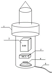
[0016] An electric soldering iron with a time telling device comprises a soldering iron main body, a clock display, a microcontroller, a loudspeaker, and wires. The clock display is embedded in the upper part of the handle part of the soldering iron body, the controller is installed in the middle of the handle part of the soldering iron body, and the lower part of the clock display; the speaker is installed in the lower part of the soldering iron body; the wire is connected to the bottom of the soldering iron body.

[0017] Because of the timing controlled by the microcontroller, the present invention can accurately calculate the time spent from starting up to "now", so that the heating of the soldering iron can be better estimated according to the heating model of the soldering iron, and the soldering iron maintains a high temperature for too long Automatically cut off the power supply at the time, which can better make up for the safety hazard of the soldering iron.

Embodiment 2

[0019] An electric soldering iron with a time telling device, the heating core adopts an iron core; the clock display adopts an LCD display. More innovative and practical.

[0020] The adoption of the iron core can enhance the plasticity of the overall manufacturing, making the cost of the present invention lower; at the same time, the LCD display screen also clearly shows the auxiliary reminder of the time last night. Comprehensively play the role of reducing the safety hazard of soldering iron.

[0021] In actual use, the electric wire is inserted into the mains plug, then the soldering iron starts to work, and the microprocessor also starts to calculate the working time of the soldering iron. When the working time is too long, the microprocessor controls the loudspeaker to give a loud reminder to remind the user to turn off the power or reduce the temperature of the soldering iron, thereby protecting the soldering iron and reducing the possibility of safety accidents.


PUM


Abstract

The invention belongs to the electronic information and electric tool technical field and specifically provides an electric soldering iron with a timing device. The electric soldering iron with the timing device comprises a soldering iron main body (1), a clock display screen (2), a microcontroller (3), a loudspeaker (4) and an electric wire (5). The clock display screen (2) is embedded in the handle of the soldering iron main body (1) at the upper position, the microcontroller (3) is mounted at the middle of the handle of the soldering iron main body (1) and at the lower part of the clock display screen (2); the loudspeaker (4) is mounted at the lower part of the soldering iron main body (1); the electric wire (5) is connected to the bottom of the soldering iron main body (1); the safety degree of the existing electric soldering iron is low after the user leaving while the existing electric soldering iron has no timing turnoff and the timing reminding function for what the using time detection device is not equipped. The timing device and the display screen are controlled by the microcontroller for effectively reminding the using time for the users, and the soldering iron can be automatically turned off while not used for a long time.

Description

technical field [0001] The invention belongs to the technical field of electronic information and electrical tools, and in particular relates to an electric soldering iron with a time telling device. Background technique [0002] With the rapid development of electronic technology, more and more people are interested in electronic technology and IT technology, which directly promotes the popularity of electronic production tools and the rise of electronic DIY enthusiasts. [0003] At present, there are more and more people who like to solder and make electronics by themselves, so tools such as electric soldering irons and soldering tin are becoming more and more popular. The main principle of the current electric soldering iron is to use electric current to heat the heating element, thereby generating heat. There are two kinds of electric soldering irons with ceramic core and metal core that are more common. The principle is to use the mains electricity to heat the heating...

Claims


Application Information

Patent Timeline
Patent Type & Authority Applications(China)
IPC IPC(8): B23K3/03
CPCB23K3/03
Inventor 巨杰
Owner 西安思创达通讯科技有限责任公司
Learn More