Soldering iron head

A technology for soldering iron tips and soldering tips, which is applied to soldering irons, welding positions, metal processing equipment, etc., can solve the problem that electric soldering irons cannot meet the requirements of correct acquisition of soldering tip temperature sensing lines and miniaturization of soldering irons, and achieves not easy to break and response speed. Fast, high-intensity effects

Active Publication Date: 2015-05-27
QUICK INTELLIGENT EQUIP CO LTD
View PDF9 Cites 6 Cited by
  • Summary
  • Abstract
  • Description
  • Claims
  • Application Information

AI Technical Summary

Problems solved by technology

[0004] The technical problem to be solved by the present invention is: in order to overcome the deficiency that the existing electric soldering iron cannot meet the requirements of correctly collecting the temperature of the solde...

Method used


Image

  • Soldering iron head
  • Soldering iron head
  • Soldering iron head

Examples


Embodiment Construction

[0021] The present invention is described in further detail now in conjunction with accompanying drawing. These drawings are all simplified schematic diagrams, which only illustrate the basic structure of the present invention in a schematic manner, so they only show the configurations related to the present invention.

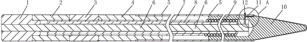
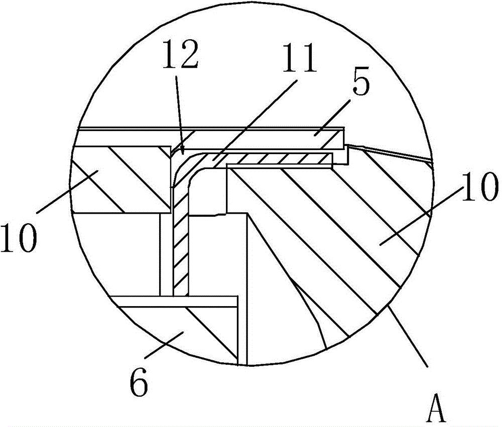
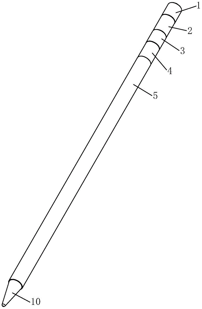
[0022] Such as figure 1 , figure 2 As shown, a soldering iron tip of the present invention includes a soldering tip 10, an outer tube 5 and a sensing wire 11, the soldering tip 10 is installed at one end of the outer tube 5, the sensing wire 11 is arranged inside the outer tube 5, and the side of the soldering tip 10 is provided There is a through hole 12, one end of the sensing wire 11 is drawn out from the through hole 12 and is in contact with the outer surface of the welding head 10, and the end of the sensing wire 11 in contact with the outer surface of the welding head 10 is welded with the inner wall of one end of the outer tube 5 to form a thermocoup...


PUM


Abstract

The invention relates to a soldering iron head, which comprises a welding head, an outer tube and a sensing wire, wherein the welding head is arranged at one end of the outer tube, the sensing wire is arranged inside the outer tube, the side face of the welding head is provided with a groove and a through-hole, one end of the sensing wire is led out from the groove and the through-hole and contacts with the outer surface of the welding head, and is welded with the outer tube to form a temperature measuring end of a thermocouple, the sensing wire and the outer tube respectively constitute two poles of the thermocouple. According to the soldering iron head disclosed by the invention, the sensing wire directly contacts with the surface of the welding head, the collected temperature is close to the real temperature, and the reaction rate to the temperature is rapid; the temperature sensing part and the heating wire heating part are fused together, the miniaturization of the whole soldering iron head is realized, the strength of the whole welding head is still high, and is not easy to break.

Description

technical field [0001] The invention relates to a welding device, in particular to a soldering iron head. Background technique [0002] In order to enhance the functionality of the welding station, a welding station with a sensor has appeared on the market. The principle is that one end of the sensing line is connected to the welding head of the welding station, and the other end is connected to the signal receiving device. While welding, Receive solder joint related information through the sensing line. Generally, the sensing line adopts the external or internal connection type. Specifically, the external connection type uses one end of the sensing line to connect to the welding head, pass through the appearance of the welding head, and then connect to the receiving device. In this way, the wire is directly exposed to the appearance, giving The welding operation brings some inconvenience, and it is also easy to cause the sensing line to fall off. Another way is to protect ...

Claims


Application Information

Patent Timeline
IPC IPC(8): B23K3/03
CPCB23K3/025B23K3/0392
Inventor 戚国强姜加伟孙红兵
Owner QUICK INTELLIGENT EQUIP CO LTD
Why Eureka
Try Eureka