Screw-driven type outer circle centering clamping device

A technology of screw drive and clamping device, applied in the direction of clamping device, positioning device, clamping, etc., can solve the problems of chuck wear, difficult disassembly, large volume, etc., and achieves low production cost, convenient production, and simple production process. Effect

Inactive Publication Date: 2015-05-27
XIAN ZHONGZHI HUIZE PHOTOELECTRIC TECH
View PDF0 Cites 12 Cited by
  • Summary
  • Abstract
  • Description
  • Claims
  • Application Information

AI Technical Summary

Problems solved by technology

Under the guide part of the three jaws on the three-jaw chuck, there are threads that mesh with the plane threads on the back of the bevel gear. When the small bevel gear is turned with a wrench through the square hole, the bevel gear rotates, and the plane threads on the back simultaneously Drive the three jaws to approach or withdraw from the center to clamp workpieces with different diameters. However, if the three-jaw chuck is used for a long time, the chuck will wear out, and the three jaws will also appear bell-mouthed, making the three jaws deviate from the chuck. In addition, the three-jaw chuck still has the disadvantages of large volume, heavy weight, and difficult disassembly.

Method used


Image

  • Screw-driven type outer circle centering clamping device
  • Screw-driven type outer circle centering clamping device

Examples


Embodiment Construction

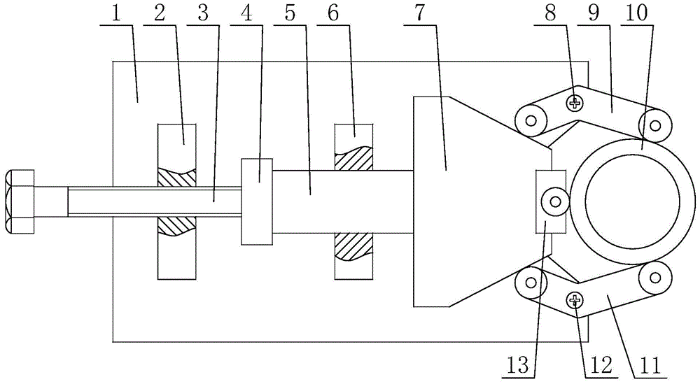
[0022] Such as figure 1 and figure 2 A screw-driven outer circle centering clamping device shown includes a rectangular base 1 with a V-shaped groove 1-1 at one end, a guide rod 5 that moves freely back and forth in a guide rod seat 6, and is used to drive the The screw rod 3 of the guide rod 5 and the screw rod seat 2 that cooperates with the screw rod 3 to form a threaded pair also include a clamping arm one 9, a clamping arm two 11 and a top block 13 that cooperate with each other for clamping the workpiece 10; The upper side of one end of the rectangular base 1 is fixedly provided with a screw base 2, the screw base 2 is provided with the screw 3, the middle part of the rectangular base 1 slides through the guide rod base 6 to be provided with a guide rod 5, the screw rod One end of 3 is rotatably connected with one end of the guide rod 5 through the connecting seat 4, and the other end of the guide rod 5 is fixedly provided with an inclined-plane push head 7, which is u...


PUM


Abstract

The invention discloses a screw-driven type outer circle centering clamping device. The device comprises a rectangular base, a guide rod, a screw, a screw seat, a first clamping arm, a second clamping arm and a propping block; the first clamping arm and the second clamping arm are matched with each other to clamp a component; the screw seat is fixedly arranged at the upper side of one end of the rectangular base; the screw is arranged in the screw seat; the guide rod is glidingly arranged in the middle part of the rectangular base through the guide rod seat; one end of the screw is rotatably connected with one end of the guide rod through the connecting seat, and while the other end of the guider rod is fixedly equipped with a bevel push; the propping block for propping the component is fixedly arranged at the front end of the bevel push head; the first clamping arm and the second clamping arm are respectively rotatably arranged at two sides of a V-shaped groove, on the other end of the rectangular base. The device has the characteristics of being reasonable in design, simple in structure, centering and clamping an outer circle, and being large in force increasing ratio, independent to lock, convenient to operate, long in service life, low in production cost, and convenient to popularize and use.

Description

technical field [0001] The invention belongs to the technical field of mechanical processing, and relates to a clamping device, in particular to a screw-driven clamping device with an outer circle centering function. Background technique [0002] At present, in the machining process of shaft workpieces, the most commonly used clamping tool is a three-jaw chuck because the outer contour of the shaft workpiece has a certain radian. The three-jaw chuck is composed of a chuck body, movable jaws and jaw driving mechanism. Under the guide part of the three claws on the three-jaw chuck, there are threads that mesh with the plane threads on the back of the bevel gear. When the small bevel gear is turned with a wrench through the square hole, the bevel gear rotates, and the plane threads on the back simultaneously Drive the three jaws to approach or withdraw from the center to clamp workpieces with different diameters. However, if the three-jaw chuck is used for a long time, the chu...

Claims


Application Information

Patent Timeline
IPC IPC(8): B23Q3/00
CPCB23Q3/00B23Q2703/10
Inventor 侯鹏
Owner XIAN ZHONGZHI HUIZE PHOTOELECTRIC TECH
Why Eureka
Try Eureka