Adjustment method of magnetic field intensity of magnetron

A technology of magnetic field strength and adjustment method, applied in ion implantation plating, metal material coating process, coating and other directions, can solve the problems of uneven corrosion rate, poor film thickness uniformity, uneven electron e movement, etc. Achieve the effect of improving utilization and good uniformity

Active Publication Date: 2015-05-27
BEIJING NAURA MICROELECTRONICS EQUIP CO LTD
View PDF4 Cites 9 Cited by
  • Summary
  • Abstract
  • Description
  • Claims
  • Application Information

AI Technical Summary

Problems solved by technology

[0005] However, the above-mentioned magnetron sputtering equipment inevitably has the following problems in actual use, that is, because the movement of electrons e on the surface of the target 1 is affected by the magnetic field generated by the magnetron 2, this causes the magnetron 2 When the magnetic field generated near the surface of the target 1 is not uniform, the movement of the electron e on the surface of the target 1 is also not uniform, resulting in the Ar + The inhomogeneous distribution on the surface of the target 1 makes the corrosion rate of different regions on the target inhomogeneous, that is to say, in Ar + In the densely distributed area, the target is covered by Ar + Concentrated bombardment, so that the corrosion rate of the target in this area is greater than that of the target in other areas, and after the target in this area is completely corroded, the target can no longer be used, resulting in the loss of the target The utilization rate is low and a lot of waste is generated
At the same time, the Ar on the surface of target 1 + Uneven distribution will also make Ar + When bombarding the target 1, the target atoms or molecules detached from the surface of the target 1 and deposited on the substrate 3 are distributed unevenly on the substrate 3, resulting in a relatively uniform thickness of the film deposited on the substrate 3. Difference

Method used


Image

  • Adjustment method of magnetic field intensity of magnetron
  • Adjustment method of magnetic field intensity of magnetron
  • Adjustment method of magnetic field intensity of magnetron

Examples


Embodiment Construction

[0023] In order for those skilled in the art to better understand the technical solution of the present invention, the method for adjusting the magnetic field strength of the magnetron provided by the present invention will be described in detail below in conjunction with the accompanying drawings.

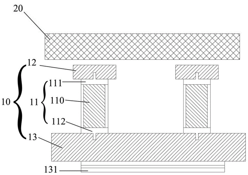
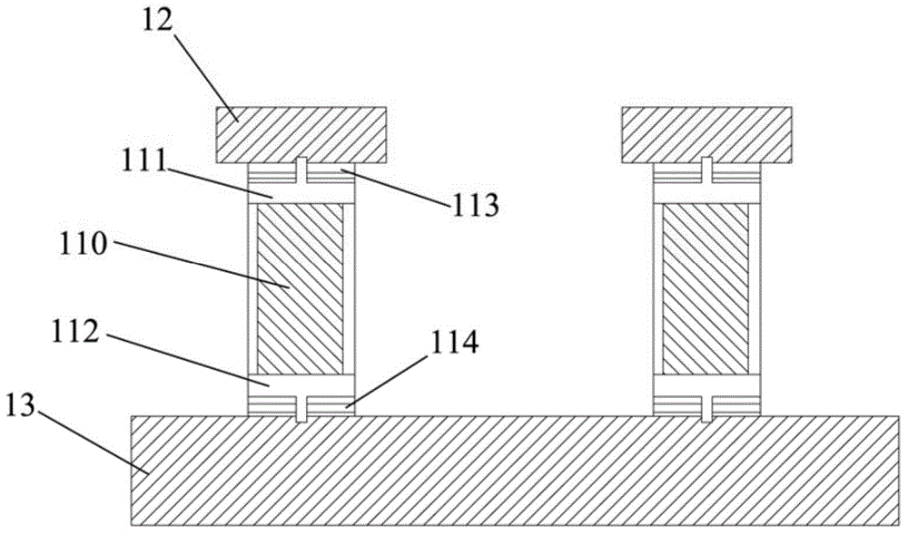
[0024] Firstly, it should be explained that in this embodiment, the direction from the magnetron 10 to the target 20 is defined as "up", and the direction from the target 20 to the magnetron 10 is defined as "down".

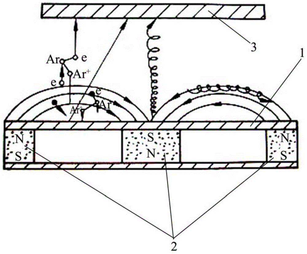
[0025] figure 2 The method for adjusting the magnetic field strength of the magnetron provided by the embodiment of the present invention is a schematic diagram of adjusting the magnetic field strength of the magnetron 10 . Please see figure 2 , in the magnetron sputtering equipment, the magnetron 10 is arranged below the target 20 for generating a magnetic field on the upper surface of the target 20, and between the magnetron 10 and the target 20 is filled with d...


PUM

PropertyMeasurementUnit
magnetic susceptibilityaaaaaaaaaa

Abstract

The invention relates to an adjustment method of magnetic field intensity of a magnetron, wherein the magnetron comprises a plurality of magnet assemblies arranged successively. Each magnet assembly comprises a magnet, and an upper cover and a lower cover which are arranged respectively on upper end surface and lower end surface of the magnet. The adjustment method includes a step of, with maintenance of constant total height of each magnet assembly, changing the heights of the magnet, the upper cover and the lower cover of the each magnet assembly in a to-be-adjusted zone in the magnetron, or changing proportion of the heights of any two of the three heights in the total height of the total height of the magnet assembly, so that the magnetic field intensity in the to-be-adjusted zone in the magnetron is enhanced or weakened. By means of the adjustment method, a uniform magnetic field intensity in all zones in an upper surface of a target material can be obtained, and further particles can bombard the target material uniformly during a magnetron sputtering deposition technology process, so that the target material is uniformly corroded during the technology process, thereby increasing utilization rate of the target material and achieving a better uniformity of a thin film deposited onto a to-be-processed workpiece.

Description

technical field [0001] The invention relates to the field of semiconductor equipment manufacturing, in particular to a method for adjusting the magnetic field strength of a magnetron. Background technique [0002] In the semiconductor process, sputtering technology is widely used to deposit thin films on substrates. The principle is that high-energy electrons accelerated by an electric field collide with atoms in the process gas, such as Ar atoms in argon, and ionize Ar. + and another electron; among them, the electron flies to the substrate and continuously collides with Ar atoms in the process, ionizing more Ar + and electrons; and Ar + Under the action of the electric field, the surface of the target is bombarded, so that the target atoms or molecules on the surface of the target are detached from the surface of the target and deposited on the substrate, thereby forming a thin film. [0003] The above-mentioned sputtering technology has the following problems in actual ...

Claims


Application Information

Patent Timeline
Patent Type & Authority Applications(China)
IPC IPC(8): C23C14/35C23C14/54
Inventor 张伟王厚工杨玉杰郑友山
Owner BEIJING NAURA MICROELECTRONICS EQUIP CO LTD
Why Eureka
Try Eureka