A kind of magnetron sputtering device and method

A magnetron sputtering device and magnetic field technology, applied in the field of magnetron sputtering, can solve the problem of low utilization rate of target materials, achieve the effects of uniform distribution, reduce production cost, and prolong use time

Active Publication Date: 2016-03-09
BOE TECH GRP CO LTD +1
View PDF6 Cites 0 Cited by
  • Summary
  • Abstract
  • Description
  • Claims
  • Application Information

AI Technical Summary

Problems solved by technology

[0007] Embodiments of the present invention provide a magnetron sputtering device and method, which are used to solve the problem of low target utilization in the prior art when magnetron sputtering technology is used for coating

Method used


Image

  • A kind of magnetron sputtering device and method
  • A kind of magnetron sputtering device and method
  • A kind of magnetron sputtering device and method

Examples


Embodiment Construction

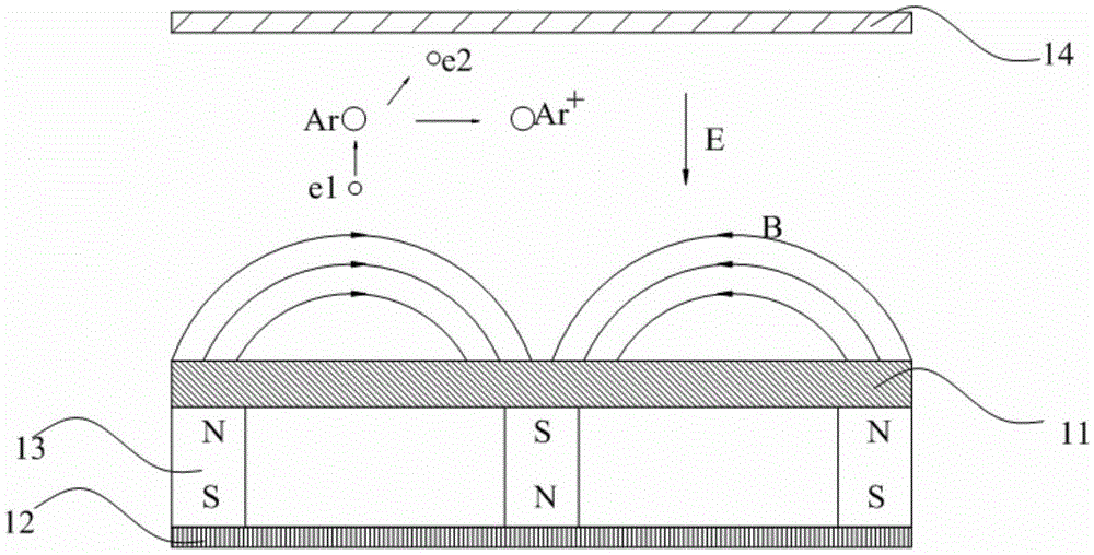
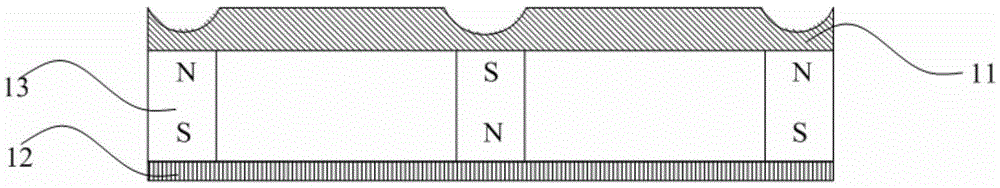
[0029] Embodiments of the present invention provide a magnetron sputtering device and method, which are used to solve the problem of low target utilization in the prior art when magnetron sputtering technology is used for coating.

[0030] The following will clearly and completely describe the technical solutions in the embodiments of the present invention with reference to the accompanying drawings in the embodiments of the present invention. Obviously, the described embodiments are only some, not all, embodiments of the present invention. Based on the embodiments of the present invention, all other embodiments obtained by persons of ordinary skill in the art without making creative efforts belong to the protection scope of the present invention.

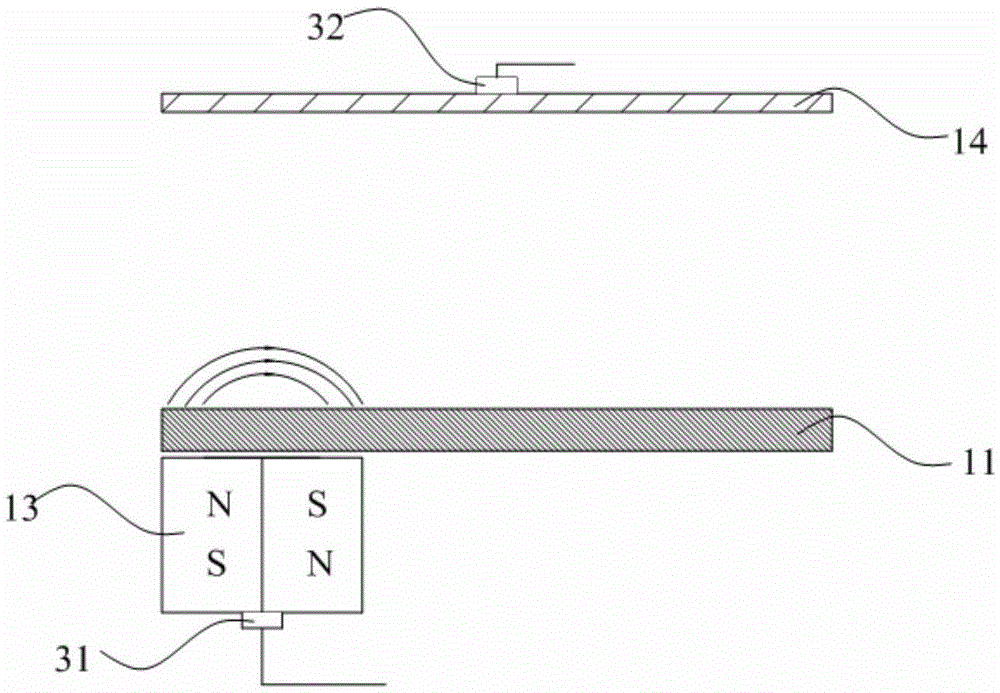
[0031] An embodiment of the present invention provides a magnetron sputtering device, see image 3 ; image 3 It is a schematic cross-sectional structure diagram of a magnetron sputtering device provided by an embodiment of the pr...


PUM


Abstract

The invention provides a magnetron sputtering apparatus and a method, which can be used for solving the problem that in the prior art, when a magnetron sputtering technology is used for coating a film, the utilization rate of a target material is low. The magnetron sputtering apparatus comprises a substrate on which film is formed, the target material arranged by facing the substrate on which film is formed, and a magnet assembly positioned at one side of the target material opposite to the substrate on which film is formed, and the magnetron sputtering apparatus also comprises a first driving structure connected to one end of the magnet assembly far from the target material, the first driving structure is used for bearing the magnet assembly, the magnetron sputtering apparatus is capable of controlling the relative position of the magnet assembly and the target material through the first driving structure, and then is capable of controlling the scope of the magnetic field which is corresponded to the substrate on which film is formed, covered on the surface of the target material and generated by the magnet assembly.

Description

technical field [0001] The invention relates to the technical field of magnetron sputtering, in particular to a magnetron sputtering device and method. Background technique [0002] The so-called magnetron sputtering refers to adding an orthogonal magnetic field and a driving electric field between the cathode (usually the target) and the anode (usually the substrate mounting seat on which the substrate to be filmed or the wall of the coating chamber is installed), and the vacuum coating The cavity is filled with the required inert gas (usually argon), and the argon is ionized into argon ions (positively charged) and electrons. The argon ions are accelerated to bombard the target under the action of the driving electric field, sputtering out a large number of target particles , neutral target particles (atoms or molecules) are deposited on the film-forming substrate to form a film. [0003] see figure 1 , figure 1 It is a schematic diagram of the working principle of the ...

Claims


Application Information

Patent Timeline
Patent Type & Authority Patents(China)
IPC IPC(8): C23C14/35
Inventor 张启平方旭东王伟孙文波
Owner BOE TECH GRP CO LTD
Why Eureka
Try Eureka