
Full-automatic wall tile and floor tile laying machine

A fully automatic, laying machine technology, applied in the direction of construction, building structure, etc., can solve the problems that affect the development and progress of the industry, the perfection is not satisfactory, the overall quality is not high, and achieve significant economic and social benefits, precise paste, The effect of saving human resources

Inactive Publication Date: 2015-05-27
SHAOXING COUNTY LONGHUA TOOLS
View PDF0 Cites 10 Cited by
  • Summary
  • Abstract
  • Description
  • Claims
  • Application Information

AI Technical Summary

Problems solved by technology

[0002] With the improvement of people's living standards, the requirements for the living environment are also constantly improving. The interior decoration of buildings is particularly important. For example, wall and floor tiles that can reflect the nobility and magnificence of the interior room, and are durable, are very popular among people. However, because most of its materials are fired bricks, although it has a certain hardness, its fastness is not enough. In addition, it is already a finished brick. If it is to be fixed on the wall or the ground, it must be fixed on it with a medium, but this process is harmful to the operation. The requirements for personnel are very high, because it depends entirely on the experience and ability of the operator to determine the fastness and flatness of the wall and floor tiles, so after this work is completed, the perfection of the entire wall or the entire floor is not satisfactory
Due to the backward technology and method of pasting wall and floor tiles, the overall quality of the current decoration industry is not high, which affects the development and progress of the industry.

Method used


Image

  • Full-automatic wall tile and floor tile laying machine
  • Full-automatic wall tile and floor tile laying machine
  • Full-automatic wall tile and floor tile laying machine

Examples


Embodiment Construction

[0014] Embodiments of the present invention will be further described below in conjunction with the accompanying drawings.

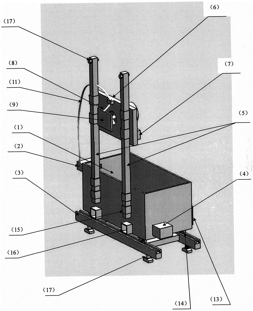
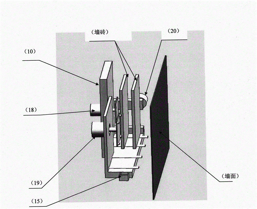
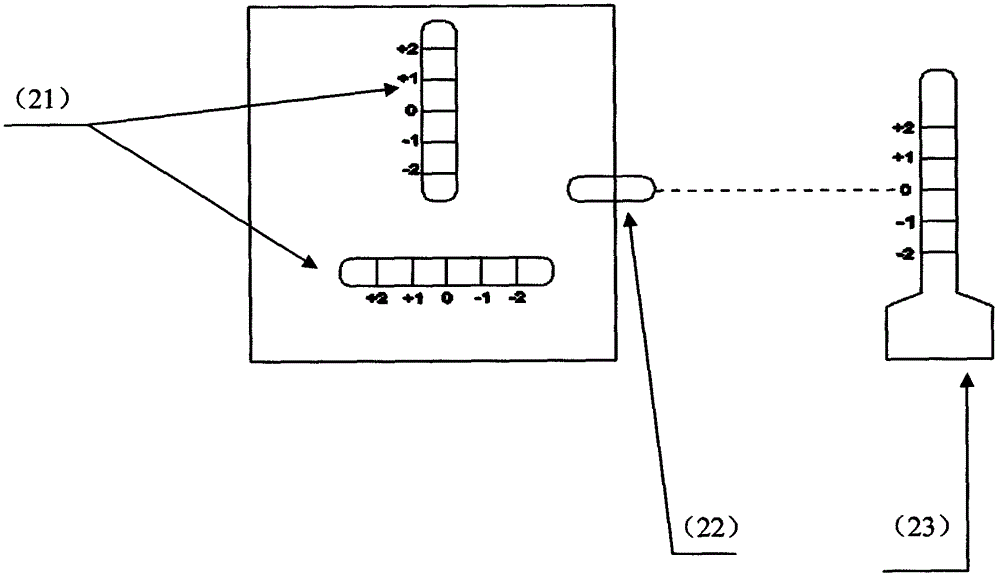
[0015] Such as figure 1 Shown: a fully automatic wall and floor tile laying machine, which includes: mixer 1, mud pump 20, moving guide rail 3, lower driving mechanism 4, guide post 5, mounting seat 6, upper driving mechanism 7, filling port 8, vibration Mechanism 9, wall and floor tile laying frame 10, conduit 11 multidirectional level 12, control system 13; mixer 1 is installed on the moving guide rail 3, the lower driving mechanism 4 and mud pump 2 are fixed on both sides of the mixer 1, and the guide column 5 is fixed On the front side of the mixer 1, the installation seat 6 is installed on the guide column 5, and the upper driving mechanism 7 is fixed in the installation seat 6; the upper part of the installation seat 6 is provided with a filling port 8, and a vibration mechanism 9 and a replaceable wall are arranged in the middle , Floor tile layi...


PUM


Abstract

The invention discloses a full-automatic wall tile and floor tile laying machine. The full-automatic wall tile and floor tile laying machine comprises a blender, a slurry pump, a mobile lead rail, a guide post, an upper drive mechanism, a lower drive mechanism, a mounting base, a pouring hole, a vibrating mechanism, a wall tile and floor tile laying rack, a conduit, a multi-directional gradienter and a control system; the blender is arranged on the mobile lead rail, the lower drive mechanism and slurry pump are fixed at two sides of the blender, the guide post is fixed at the front side of the blender, the mounting base is arranged on the guide post, and the upper drive mechanism is fixed in the mounting base; the pouring hole is formed in the upper part of the mounting base, and the middle is provided with the vibrating mechanism and the changeable wall tile and floor tile laying rack. Compared with the prior art, the full-automatic wall tile and floor tile laying machine uses an execution mechanism controlled by a control program, the smearing consistency between the wall surface and floor to be bonded with wall tiles and floor tiles is very good, the positions of the wall tiles and floor tiles can be precisely located through machinery, die and digital locating, and the bonding is precise. Through using the machinery to replace manpower, the efficiency is improved, the manpower resource is saved, the bonding cost is lowered, and the economical benefit and social benefit are obvious.

Description

technical field [0001] The invention relates to a fully automatic wall and floor tile laying machine, especially related to construction, decoration machinery and related equipment. Background technique [0002] With the improvement of people's living standards, the requirements for the living environment are also constantly improving. The interior decoration of buildings is particularly important. For example, wall and floor tiles that can reflect the nobility and magnificence of the interior room, and are durable, are very popular among people. However, because most of its materials are fired bricks, although it has a certain hardness, its fastness is not enough. In addition, it is already a finished brick. If it is to be fixed on the wall or the ground, it must be fixed on it with a medium, but this process is harmful to the operation. The requirements for personnel are very high, because it depends entirely on the experience and ability of the operator to determine the f...

Claims


Application Information

Patent Timeline
IPC IPC(8): E04F21/18E04F21/22
Inventor 王仁坤王列沈润杰
Owner SHAOXING COUNTY LONGHUA TOOLS
Learn More