Vehicle power transmission device

A power transmission device and vehicle technology, which is applied to transmission parts, belts/chains/gears, mechanical equipment, etc., can solve the problems of radial thrust ball bearing self-aligning function failure, power transmission efficiency reduction, radial thrust ball Problems such as increased bearing friction

Active Publication Date: 2017-05-31
HONDA MOTOR CO LTD
View PDF5 Cites 0 Cited by
  • Summary
  • Abstract
  • Description
  • Claims
  • Application Information

AI Technical Summary

Problems solved by technology

However, when the one-way clutch is engaged to transmit torque, if the diameter of the outer member expands due to the rollers engaging in the wedge-shaped space formed between the inner member and the outer member, the inner ring and outer ring of the radial thrust ball bearing will The gap between the rings expands to create a gap between them and the balls, which may cause the self-aligning function of the radial thrust ball bearing to fail
[0005] In order to prevent this, it is only necessary to set the axial preload acting on the radial thrust ball bearing to be large so that the balls are strongly clamped between the inner ring and the outer ring. However, if this is the case, Then there is a problem that the friction of the radial thrust ball bearing increases and the power transmission efficiency decreases.

Method used


Image

  • Vehicle power transmission device
  • Vehicle power transmission device
  • Vehicle power transmission device

Examples


Embodiment Construction

[0053] Below, based on Figure 1 to Figure 11 Embodiments of the present invention will be described.

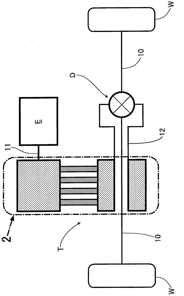
[0054] Such as figure 1 As shown, the vehicle power transmission device that transmits the driving force of the engine E to the drive wheels W, W through the left and right axles 10 , 10 includes a crank-type continuously variable transmission T and a differential D.

[0055] Next, based on Figure 2 ~ Figure 6 The structure of the continuously variable transmission T will be described.

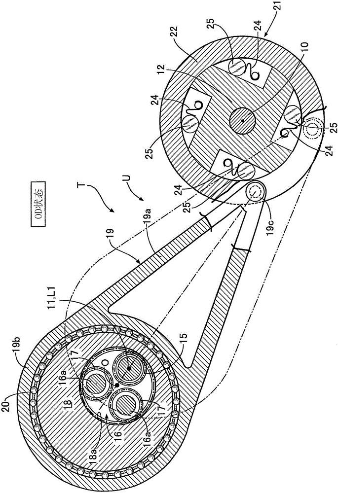
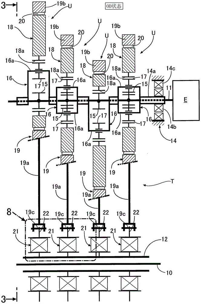
[0056] Such as figure 2 and image 3 As shown, the continuously variable transmission T of this embodiment is obtained by stacking a plurality of (four in the embodiment) transmission units U having the same structure in the axial direction. The input shaft 11 and the common output shaft 12 are transmitted to the output shaft 12 after the rotation of the input shaft 11 is decelerated or accelerated.

[0057] Hereinafter, the configuration of one transmission unit U will be described ...


PUM


Abstract

The present invention provides a vehicle power transmission device which can maintain an aligning function without increasing the preload of a radial thrust bearing of a one-way clutch. The radial thrust bearing (34)possesses an inner ring (36) which rotates integrally with an output shaft (12), and forms an annular first rolling surface (S1) located at the radial inner side and an annular fourth rolling surface (S4) located at the radial outer side; an outer ring (35) rotating integrally with a swinging rod (22) and forming an annular second rolling surface (S2) located at the radial outer side and an annular third rolling surface (S3) located at the radial inner side of the fourth rolling surface (S4); a plurality of first rolling bodies (37i) configured between the first and second rolling surfaces (S1,S2), and a plurality of second rolling bodies (37o) configured between the third rolling surface (S3) and the fourth rolling surface (S4).

Description

technical field [0001] The present invention relates to a power transmission device for a vehicle, wherein a continuously variable transmission that transmits the rotation of an input shaft connected to a drive source to an output shaft after changing the speed is provided with an eccentric member having a variable eccentricity from the axis of the input shaft, and It rotates together with the input shaft; the swing rod is pivotally supported on the outer periphery of the output shaft; the connecting rod connects the eccentric member and the swing rod and performs reciprocating motion; the one-way clutch is connected between the inner peripheral surface of the swing rod and the output shaft. A plurality of rollers are disposed between outer peripheral surfaces of the shaft; and a radial thrust bearing for supporting the swing link coaxially with respect to the output shaft. Background technique [0002] According to the following patent document 1, there is known a crank typ...

Claims


Application Information

Patent Timeline
Patent Type & Authority Patents(China)
IPC IPC(8): F16H57/021
CPCF16H57/0018F16H57/021
Inventor 吉野文博
Owner HONDA MOTOR CO LTD
Why Eureka
Try Eureka