Thermostat apparatus

Active Publication Date: 2012-05-29
FUJI BELLOWS
View PDF4 Cites 5 Cited by
  • Summary
  • Abstract
  • Description
  • Claims
  • Application Information

AI Technical Summary

Benefits of technology

[0056]FIG. 9 shows the effect of reducing the urging force in the form of the characteristics of the “coolant temperature vs. degree of opening of the main valve” of the conventional thermostat apparatus and the thermostat apparatus according to the present invention in comparison with each other.
[0057]That is, since the conventional thermostat apparatus closes the bypass port with the bypass valve, and then applies double urging forces provided by the main spring and the bypass spring, the pressure acting on the thermal extension body in the temperature sensitive movable part becomes higher, raising the melting point of the thermal extension body, so that setting a large degree of opening of the main valve requires a higher coolant temperature, causing a change in the degree of opening of the main valve with respect to the temperature of the coolant having a transition point. By way of contrast, since the thermostat apparatus according to the present invention uses a single urging force, so that a change in the degree of opening of the main valve with respect to the coolant temperature is smooth, achieving more accurate control of the coolant temperature. In addition, a large degree of opening of the main valve can be taken at a relatively low coolant temperature, so that when the coolant temperature becomes high, the cooling performance of the radiator can be demonstrated sufficiently, thus preventing the overshooting of the coolant temperature.
[0058]The reduction in urging force reduce

Problems solved by technology

Therefore, the low-temperature coolant A and the high-temperature coolant B cannot be mixed efficiently at the temperature sensitive movable part 8, making it difficult for the temperature sensitive movable part 8 to detect the temperature of the coolant C. This results in a drawback such that the liquid temperature of the coolant C cooling the engine becomes unstable, and the range of the temperature control in response to a change or

Method used


Image

  • Thermostat apparatus
  • Thermostat apparatus
  • Thermostat apparatus

Examples


first embodiment

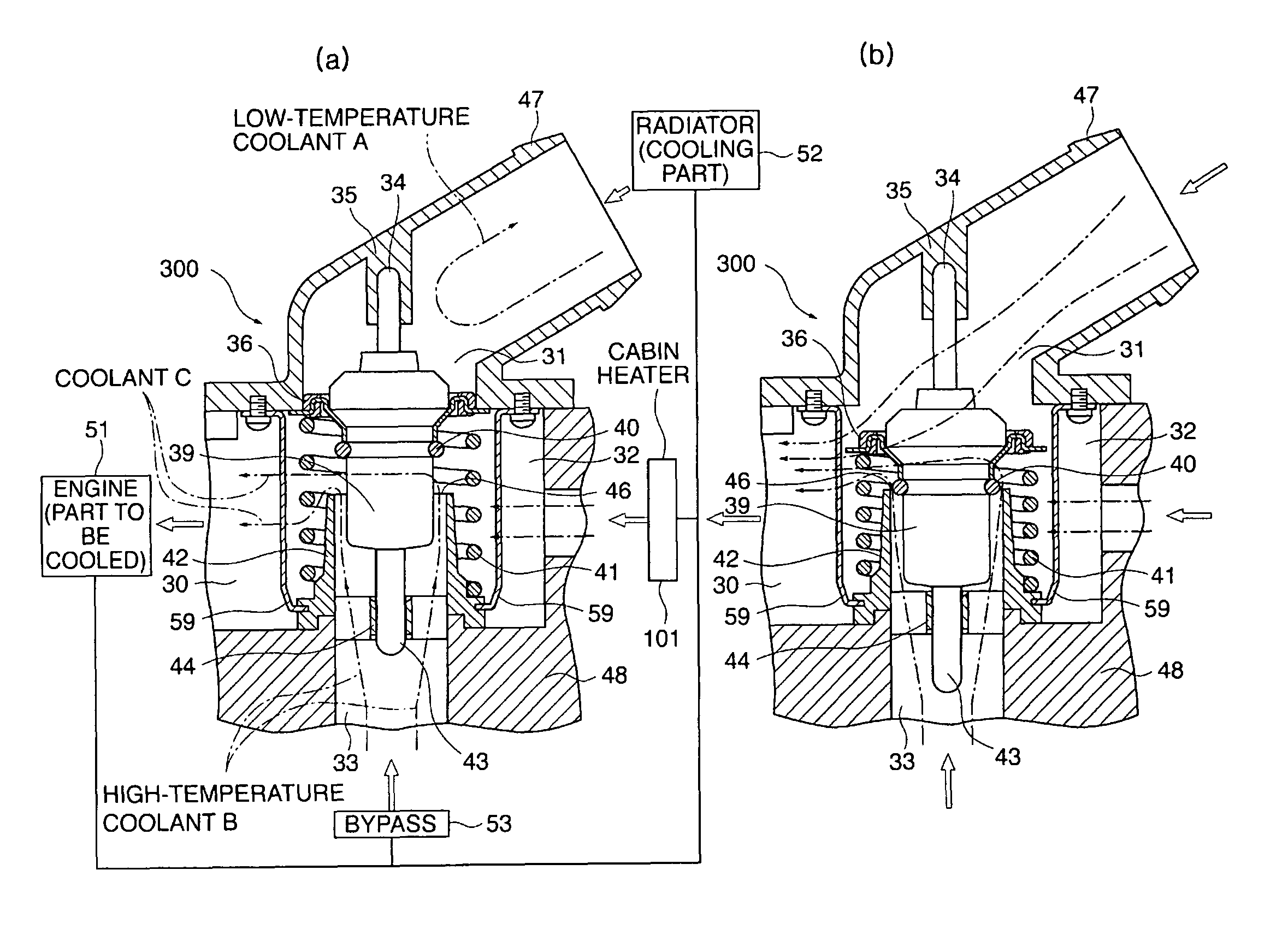
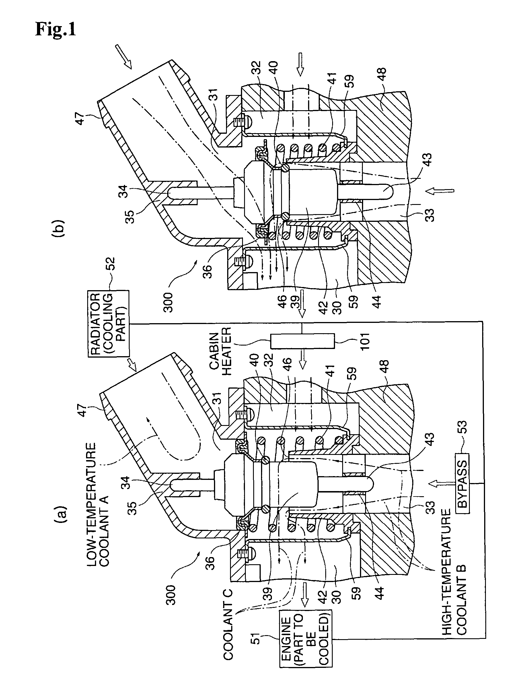
[0072]FIG. 1 shows the configuration of a thermostat apparatus 300 as the present invention.

[0073]The thermostat apparatus 300 is included in a so-called inlet control type in which a low-temperature coolant A cooled at a radiator 52 and a high-temperature coolant B supplied via a bypass 53 from an engine 51 flow into the thermostat apparatus 300, and the temperature of a coolant C which is let to flow into the engine 51 is controlled by controlling the ratio of the mixture thereof.

[0074]That is, the control system includes a bypass port 33 to which the high-temperature coolant B having passed the engine 51 is supplied via the bypass 53, and a radiator coupling port 31 to which the low-temperature coolant A that is a part of the high-temperature coolant B having passed the engine 51 and cooled at the radiator 52 is supplied from the radiator 52, and the low-temperature coolant A and the high-temperature coolant B are mixed in a housing body interior 32 to produce the coolant C. The ...

second embodiment

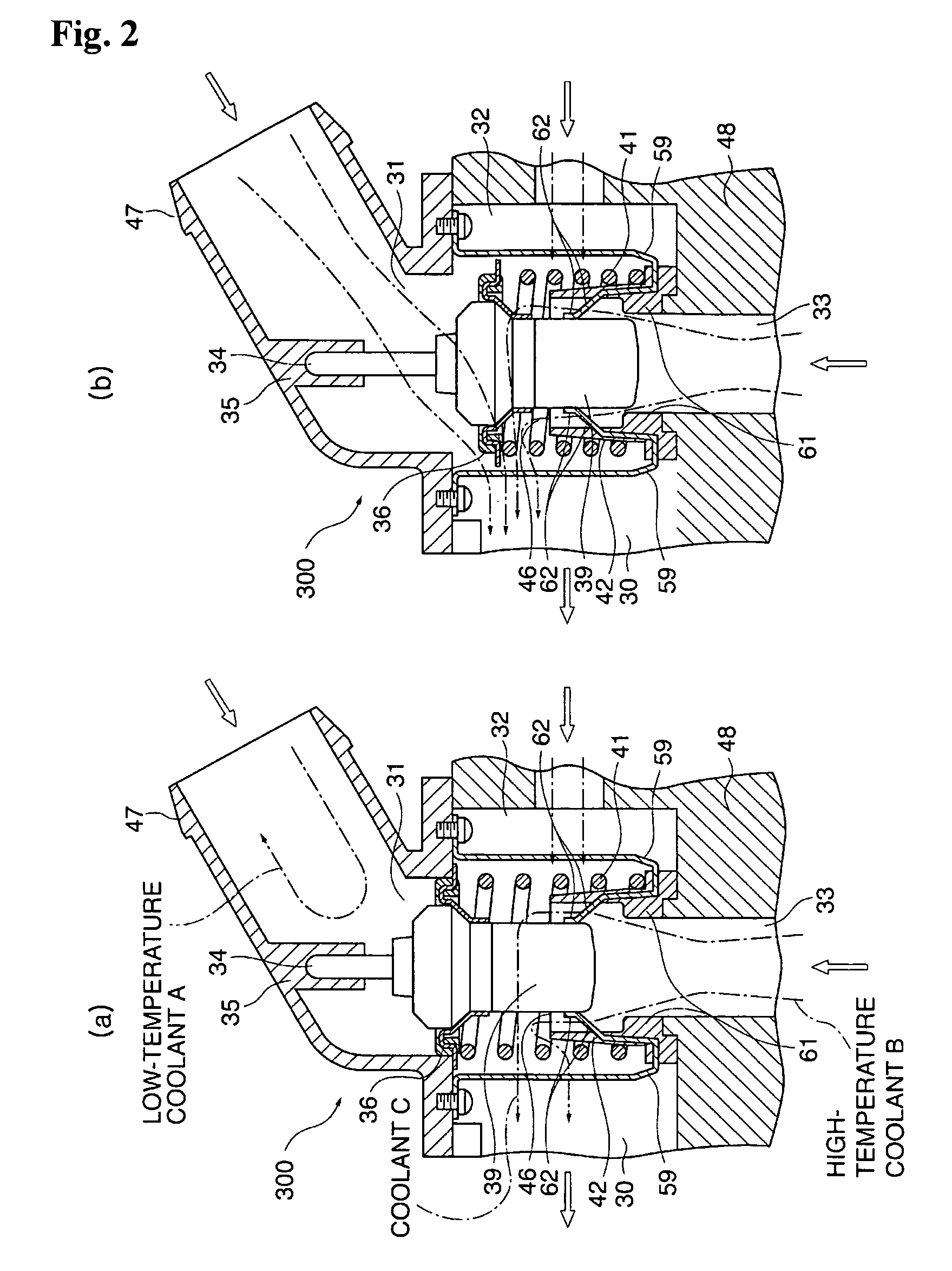
[0086]The thermostat apparatus 300 to which the present invention is adapted may be configured so that the temperature sensitive movable part 39 is inserted and guided into a support guide part 62 inside the high-temperature coolant conduit 42 as in a second embodiment shown in FIG. 2. With regard to those components and members in FIG. 2 and subsequent drawings, which are similar to the corresponding components and members in FIG. 1, same reference numerals are given to omit their descriptions below.

[0087]The support guide part 62 is formed by bending, press-working, etc. of a steel member, and is configured so as to be able to support and guide the side surface of the temperature sensitive movable part 39 disposed in an insertable manner. The support guide part 62 may be integrated with the aforementioned auxiliary fitting 59, or may be spaced apart therefrom. Multiple holes not shown are provided in the support guide part 62. The high-temperature coolant B passes through the unil...

third embodiment

[0088]The thermostat apparatus 300 to which the present invention is adapted may be adapted to a third embodiment shown in FIG. 3.

[0089]In the embodiment shown in FIG. 3, the high-temperature coolant conduit 42 is formed by a combination of a high-temperature coolant inlet passage of the housing body 48 and the support guide part 62, the ejection opening 46 is formed in the support guide part 62, and the temperature sensitive movable part 39 is supported and guided to the support guide part 62.

[0090]The support guide part 62 is provided with a plurality of unillustrated holes=ejection openings 46, so that the high-temperature coolant B supplied from the bypass port 33 directly contacts the periphery (bottom surface / side surface) of the temperature sensitive movable part 39, thereby transmitting heat, and then flows into the housing body interior 32 through the ejection openings 46. This can realize a simple and compact structure while keeping the function of the high-temperature coo...


PUM


Abstract

An apparatus includes a movable temperature sensing member capable of sensing mainly the temperature of high-temperature coolant flowing in from a high-temperature coolant port and driving toward the side of the high-temperature coolant port in dependence upon the sensed temperature; a main valve fitted integrally to the movable temperature sensing member and constructed so as to render a low-temperature coolant port and a mixing compartment openable in conformity to the driving of the movable temperature sensing member toward the side of the high-temperature coolant port, thereby controlling the inflow rate of low-temperature coolant from the low-temperature coolant port to the mixing compartment; and a high-temperature coolant inducing part communicating with the high-temperature coolant port and adapted to regulate the flow of high-temperature coolant from the high-temperature coolant port toward the surround of the movable temperature sensing member and effect outflow thereof to the mixing compartment.

Description

BACKGROUND OF THE INVENTION[0001]I. Technical Field[0002]The present invention relates to a thermostat apparatus which automatically controls a temperature of a coolant mainly cooling the engine of an automobile.[0003]II. Description of the Related Art[0004]A conventional thermostat apparatus 20, as shown in FIG. 7, has a housing body 16 including a radiator coupling port 2 to let a low-temperature coolant A, cooled by a radiator or the like, flow into a housing body interior 19, a bypass port 3 to let a high-temperature coolant B, heated by the engine, flow into the housing body interior 19, and an engine coupling port 4 to feed out a coolant C, which is a mixture of the coolants flowing through the radiator coupling port 2 and the bypass port 3, to the engine.[0005]The thermostat apparatus 20 also includes a temperature sensitive movable part 8 or a thermally expanding element which moves according to a liquid temperature in the housing body interior 19, a piston shaft 7 which has...

Claims


Application Information

Patent Timeline
IPC IPC(8): F01P7/16
CPCF01P7/16G05D23/022F01P2037/02G05D23/1333F01P2060/08F16K31/00F16K17/38
Inventor PARK, HEE WAN
Owner FUJI BELLOWS
Why Eureka
Try Eureka