Sliding plate type exhaust pipe joint for small engine test bench

A test bench and engine technology, which is applied in the direction of engine testing, pipe/pipe joint/pipe fitting, machine/structural component testing, etc. It can solve the problems of cumbersome disassembly and assembly, and achieve the effect of improving work efficiency and convenient use

Active Publication Date: 2015-05-27
GUANGXI UNIV
View PDF4 Cites 2 Cited by
  • Summary
  • Abstract
  • Description
  • Claims
  • Application Information

AI Technical Summary

Problems solved by technology

The exhaust pipe seat of the dynamometer is fixed on the test bench of the dynamometer, and the distance from the center of the crankshaft to the center of the exhaust hole on the cylinder head is different for different types of engines. It is necessary to replace the exhaust pipe joint corresponding to the engine model, and the disassembly and assembly are cumbersome

Method used


Image

  • Sliding plate type exhaust pipe joint for small engine test bench
  • Sliding plate type exhaust pipe joint for small engine test bench
  • Sliding plate type exhaust pipe joint for small engine test bench

Examples


Embodiment Construction

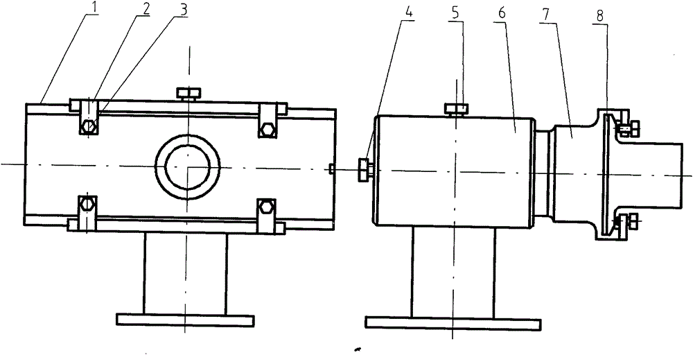
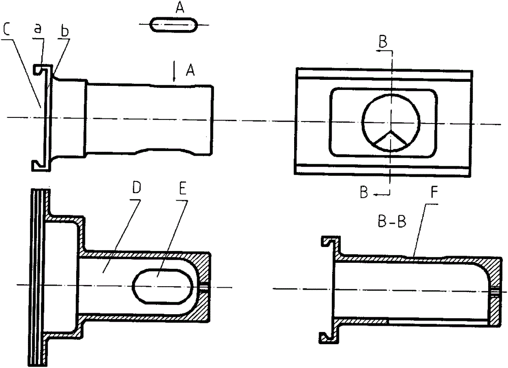
[0012] There is a chute C at the front end of the movable joint 7 of the exhaust pipe, through which the sealing plane b and the conical surface a are used to seal the exhaust gas of the engine with the gasket 8 and the slide plate 1; there is a groove F on the upper part of the movable joint 7 of the exhaust pipe, Screw the bolt 5 into the exhaust pipe seat 7 and embed it in the groove F above the movable joint 7 of the exhaust pipe, so that the movable joint 7 of the exhaust pipe is fixed on the exhaust pipe seat 6 of the test bench.

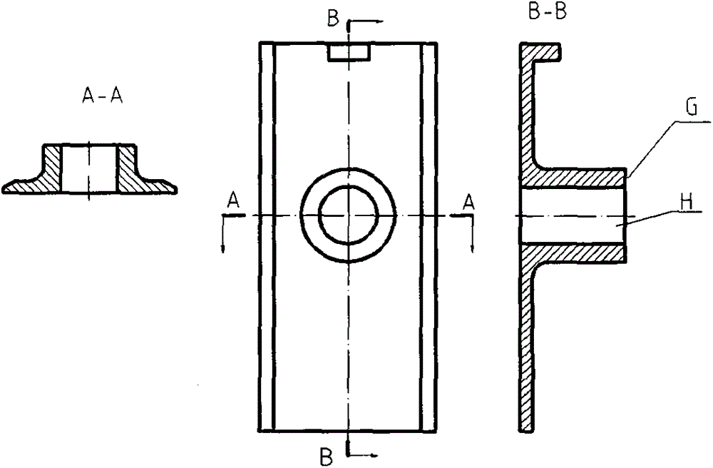
[0013] The slide plate 1 can move left and right in the chute C of the movable joint 7 of the exhaust pipe to adapt to the exhaust ports of the cylinder heads at different outlet positions of different types of engines. The bolt 3 on the slide plate positioning block 2 fixes the slide plate 1 and the movable joint 7 of the exhaust pipe.

[0014] Screw in the bolt 4 at the rear end of the movable joint 7 of the exhaust pipe, push the slide plat...


PUM


Abstract

The invention provides a sliding plate type exhaust pipe joint for a small engine test bench. The sliding plate type exhaust pipe joint consists of an exhaust pipe movable joint, a sliding plate, a sealing pad and a sliding plate locating block; the sliding plate locating block is welded on the front end face of the exhaust pipe movable joint; the sliding plate can move in a sliding chute of the exhaust pipe movable joint so as to enable a hole in the middle part to be aligned to exhaust passage ports of engine cylinder covers of different models in different positions; a sealing effect is achieved jointly through a sealing cone surface of the sliding chute of the exhaust pipe movable joint and the sealing pad; the sliding plate is fixed by nuts on the sliding plate locating block; the exhaust pipe movable joint is forward pushed by a nut which is screwed into the rear end of an exhaust pipe seat of a dynamometer to be abutted against the end face of a passage seat of the engine cylinder cover. The sliding plate type exhaust pipe joint can be applied to bench test of engines of different models without being replaced, so that the operation is simple, convenient and easy, and the working efficiency is improved.

Description

technical field [0001] The invention relates to a slide-type exhaust pipe joint for a small engine test bench, which can connect the outlet of the exhaust passage on the cylinder head of different types of engines with the exhaust pipe joint on the engine test bench, and is used for different types of engines performance test. Background technique [0002] In small engine bench tests, it is often necessary to connect the exhaust port outlet on the engine cylinder head with the exhaust pipe joint on the test bench so that the exhaust gas can be discharged into the underground flue. The exhaust pipe seat of the dynamometer is fixed on the test bench of the dynamometer, and the distance from the center of the crankshaft to the center of the exhaust hole on the cylinder head is different for different types of engines. It is necessary to replace the exhaust pipe joint corresponding to the engine model, and the disassembly and assembly are cumbersome. Contents of the invention...

Claims


Application Information

Patent Timeline
IPC IPC(8): F16L25/00F16L43/02G01M15/02
CPCF16L25/00F16L43/02G01M15/02
Inventor 韦海燕朱立靖杜勇志张琦
Owner GUANGXI UNIV
Why Eureka
Try Eureka