
Dust-removing device of cooker

A stove and ash falling technology, applied in lighting and heating equipment, etc., can solve the problems of incomplete cleaning, pollution, danger, etc., and achieve the effect of convenient ash cleaning process, convenient recycling, and energy saving

Inactive Publication Date: 2015-05-27
XUZHOU JIAGU ENVIRONMENTAL PROTECTION TECH
View PDF0 Cites 2 Cited by
  • Summary
  • Abstract
  • Description
  • Claims
  • Application Information

AI Technical Summary

Problems solved by technology

The bottom of the furnace mostly plays the role of ash discharge and ventilation. When the fuel is burned on the grate, the outside air will enter from the bottom of the furnace and enter the upper combustion chamber through the grate to support combustion. While burning, a large amount of fuel ash The slag will also fall from the furnace grate into the bottom of the furnace. If it is not cleaned in time, it will cause blockage and affect the intake of air, thus affecting the heating of the furnace. However, the existing process of cleaning the furnace is to open the furnace door and use tools to remove the fuel ash. If the slag is removed, the cleaning work is extremely inconvenient, and the cleaning is not complete. During the cleaning process, the fuel ash and slag are easy to fly, causing pollution and affecting the work of the staff.
On the other hand, the fuel ash falling from the grate also has a large amount of waste heat, if the fuel ash is removed directly, it will cause a waste of energy to a certain extent, while the hotter fuel ash It also brings certain dangers to the cleaning process.

Method used


Image

  • Dust-removing device of cooker

Examples


Embodiment Construction

[0016] The present invention will be further described below with reference to the drawings and embodiments.

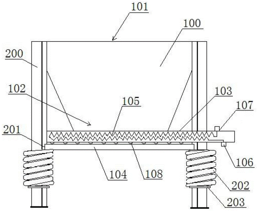
[0017] Such as figure 1 , A stove ash removal device, comprising an ash dropping trough 100, the ash dropping chute 100 is installed on a support frame, the support frame includes a plurality of support rods 200, the ash dropping chute 100 is correspondingly set up and down with an ash inlet 101 With the ash outlet 102, the ash outlet 102 is equipped with a drawing plate 103, the bottom of the drawing plate 103 is supported by a supporting plate 104, the drawing plate 103 is made of heat conductive material, and the middle of the drawing plate 103 is provided with a transmission plate. A hot cavity, a metal water pipe 105 is arranged inside the heat transfer cavity, the water inlet 106 and the water outlet 107 of the metal water pipe 105 are respectively arranged at one end of the drawing plate 103, and fuel ash falls from the grate The ash trough 100 and the drawing pl...


PUM


Abstract

The invention discloses a dust-removing device of a cooker. The dust-removing device comprises a dust falling groove, wherein the dust falling groove is arranged on a supporting frame; the supporting frame comprises a plurality of supporting rods; a dust falling inlet and a dust falling outlet are correspondingly formed in the dust falling groove up and down; the dust falling outlet is provided with a drawing plate; the bottom of the dust falling outlet is supported by a supporting plate; the drawing plate is made from a heat conduction material; a heat transfer cavity is formed in the middle part of the drawing plate; a metal water pipe is arranged in the heat transfer cavity; a water inlet and a water outlet of the metal water pipe are respectively arranged at one end of the drawing plate. Compared with the prior art, the dust-removing device provided by the invention has the advantages that due to the fact that the drawing plate is arranged at the dust falling outlet, when the dust falling groove is fully filled with fuel dust slag, the fuel dust slag can be timely removed by drawing the drawing plate, and blockage is prevented from being formed below a hearth to affect air to enter a combustion chamber.

Description

Technical field [0001] The invention relates to a stove ash removal device, belonging to the technical field of stoves. Background technique [0002] The furnace is a three-dimensional space enclosed by the furnace wall for fuel combustion. The function of the furnace is to ensure that the fuel is burned as much as possible, and the temperature of the flue gas at the exit of the furnace is cooled to the temperature allowed by the safe work of the convection heating surface. The bottom of the furnace mostly plays the role of ash production and ventilation. When the fuel is burned on the furnace, the outside air will enter from the bottom of the furnace and enter the upper combustion chamber through the furnace to support combustion. At the same time, a large amount of fuel ash will be burned. The slag will also fall into the bottom of the furnace from the grate. If it is not cleaned in time, it will cause blockage and affect the amount of air entering the furnace, thereby affecti...

Claims


Application Information

Patent Timeline
Patent Type & Authority Applications(China)
IPC IPC(8): F23J1/02
Inventor 宋忠红宋佳楠王春华
Owner XUZHOU JIAGU ENVIRONMENTAL PROTECTION TECH
Learn More