
Air conditioner and refrigerant control system and method thereof

A technology for controlling systems and refrigerants, applied in heating and ventilation control systems, refrigeration and liquefaction, space heating and ventilation, etc., and can solve problems such as violent boiling of compressor oil pools, compressor shaft wear, and compressor damage.

Inactive Publication Date: 2015-05-27
SHENZHEN MCQUAY AIR CONDITIONING
View PDF6 Cites 17 Cited by
  • Summary
  • Abstract
  • Description
  • Claims
  • Application Information

AI Technical Summary

Problems solved by technology

[0003] However, the existing commercial multi-connected pipes are getting longer and longer. In order to ensure the cooling and heating effect, it is necessary to charge more refrigerant when the outdoor unit is connected to a long pipe. When the outdoor unit is in the heating and defrosting condition At this time, if the amount of refrigerant returned to the compressor cannot be effectively controlled, the compressor oil will be diluted by the refrigerant after defrosting of the outdoor unit, and then when the compressor discharge temperature rises, the oil pool of the compressor will violently boil. Phenomenon, which will cause the diluted compressor oil to be taken away by the refrigerant, and the compressor shaft will be severely worn if it is not lubricated by the oil, and in severe cases, the compressor will be damaged

Method used


Image

  • Air conditioner and refrigerant control system and method thereof
  • Air conditioner and refrigerant control system and method thereof

Examples


Embodiment Construction

[0032] The core of the present invention is to provide a refrigerant control system and method, the refrigerant control system can effectively control the flow of refrigerant, to avoid too much refrigerant flowing into the compressor to take away the oil in the compressor, causing wear and damage to the compressor. Another core of the present invention is to provide an air conditioner including the above-mentioned refrigerant control system.

[0033] In order to enable those skilled in the art to better understand the solution of the present invention, the present invention will be further described in detail below in conjunction with the accompanying drawings and specific embodiments.

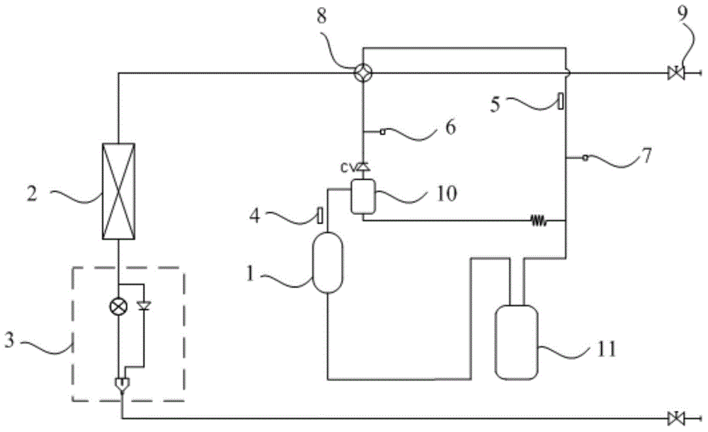
[0034] Please refer to figure 1 , figure 1 It is a structural schematic diagram of a specific embodiment of the refrigerant control system provided by the present invention.

[0035] In this embodiment, the refrigerant control system includes an acquisition device, a calculation device and a...


PUM


Abstract

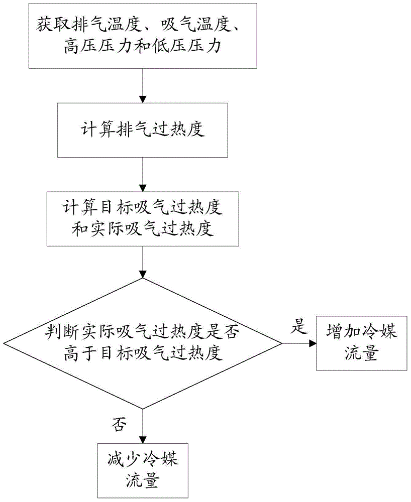
The invention discloses a refrigerant control system and a method. The refrigerant control system comprises an acquisition device, a calculating device and an electronic expansion valve, wherein the acquisition device is used for acquiring discharge temperature, suction temperature, high-pressured pressure and low-pressured pressure; the calculating device is used for calculating discharge superheat, target suction superheat and actual suction superheat, judging whether the actual suction superheat is higher than the target suction superheat or not, and sending a judgment result to the electronic expansion valve; the electronic expansion valve is used for increasing refrigerant flux when the actual suction superheat is higher than the target suction superheat, and reducing the refrigerant flux when the actual suction superheat is lower than the target suction superheat. According to the refrigerant control system provided by the invention, the acquisition and the calculation of the temperature and the pressure are utilized, so that the refrigerant volume flowing into a compressor can be ensured to be within a controlled range, and engine oil of the compressor can be prevented from being diluted by more refrigerant, and the safe and stable operation of the system is ensured. The invention also discloses an air conditioner comprising the refrigerant control system.

Description

technical field [0001] The invention relates to the application field of air conditioning equipment, in particular to a refrigerant control system and method. The present invention also relates to an air conditioner comprising the above-mentioned refrigerant control system. Background technique [0002] In the air conditioning and refrigeration system, the refrigerant refers to the working substance that circulates continuously and achieves refrigeration through its own state changes. The refrigerant is also called refrigerant. The refrigerant absorbs the heat of the cooled medium (water or air, etc.) in the evaporator and vaporizes. Condensation occurs by transferring heat to the surrounding air or water in the condenser. [0003] However, the existing commercial multi-connected pipes are getting longer and longer. In order to ensure the cooling and heating effect, it is necessary to charge more refrigerant when the outdoor unit is connected to a long pipe. When the outdoo...

Claims


Application Information

Patent Timeline
IPC IPC(8): F25B49/02F24F11/00
CPCF25B49/022F24F11/89F25B41/31
Inventor 吴喜兆程勇文
Owner SHENZHEN MCQUAY AIR CONDITIONING
Learn More