Substrate processing apparatus

Active Publication Date: 2016-12-22
DAINIPPON SCREEN MTG CO LTD
View PDF4 Cites 11 Cited by
  • Summary
  • Abstract
  • Description
  • Claims
  • Application Information

AI Technical Summary

Benefits of technology

[0023]This apparatus restricts the rinse liquid from wrapping around the to-be-processed surface while the rinse liquid moves from the second position to the first position or its vicinity in the circumferential direction of the substrate. This restricts the dilution of the chemical solution discharged onto the first position with the rinse liquid at the peripheral portion of the to-be-processed surface of the substrate. In addition, the rinse liquid has wrapped around the end face from the to-be-protected surface before the rinse liquid arrives at the first position or its vicinity in the circumferential direction of the substrate. As a result, the chemical solution that begins to wrap around the to-be-protected surface from the first position is washed away with the rinse liquid, thus diluting the chemical solution. This restricts the to-be-protected surface from being processed with the chemical solution that has wrapped aroun

Problems solved by technology

This restricts the generation of splashes that can arrive at the device region of the substrate due to a collision betw

Method used


Image

  • Substrate processing apparatus
  • Substrate processing apparatus
  • Substrate processing apparatus

Examples


first embodiment

1. First Embodiment

[0058]1.1. Configuration of Substrate Processing Apparatus 1

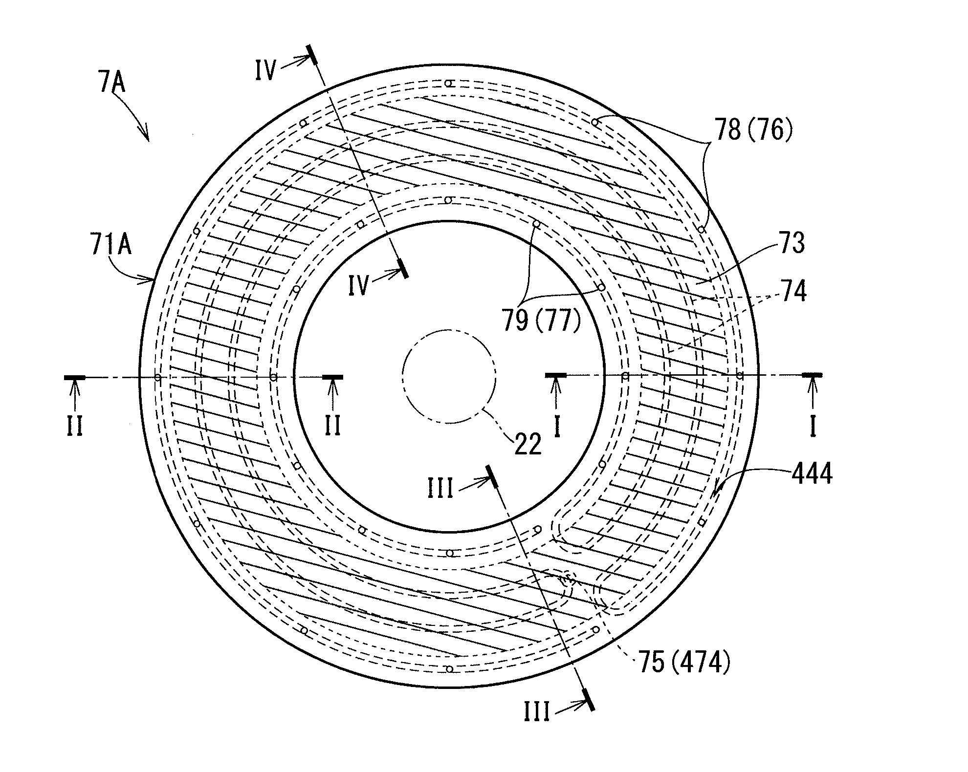
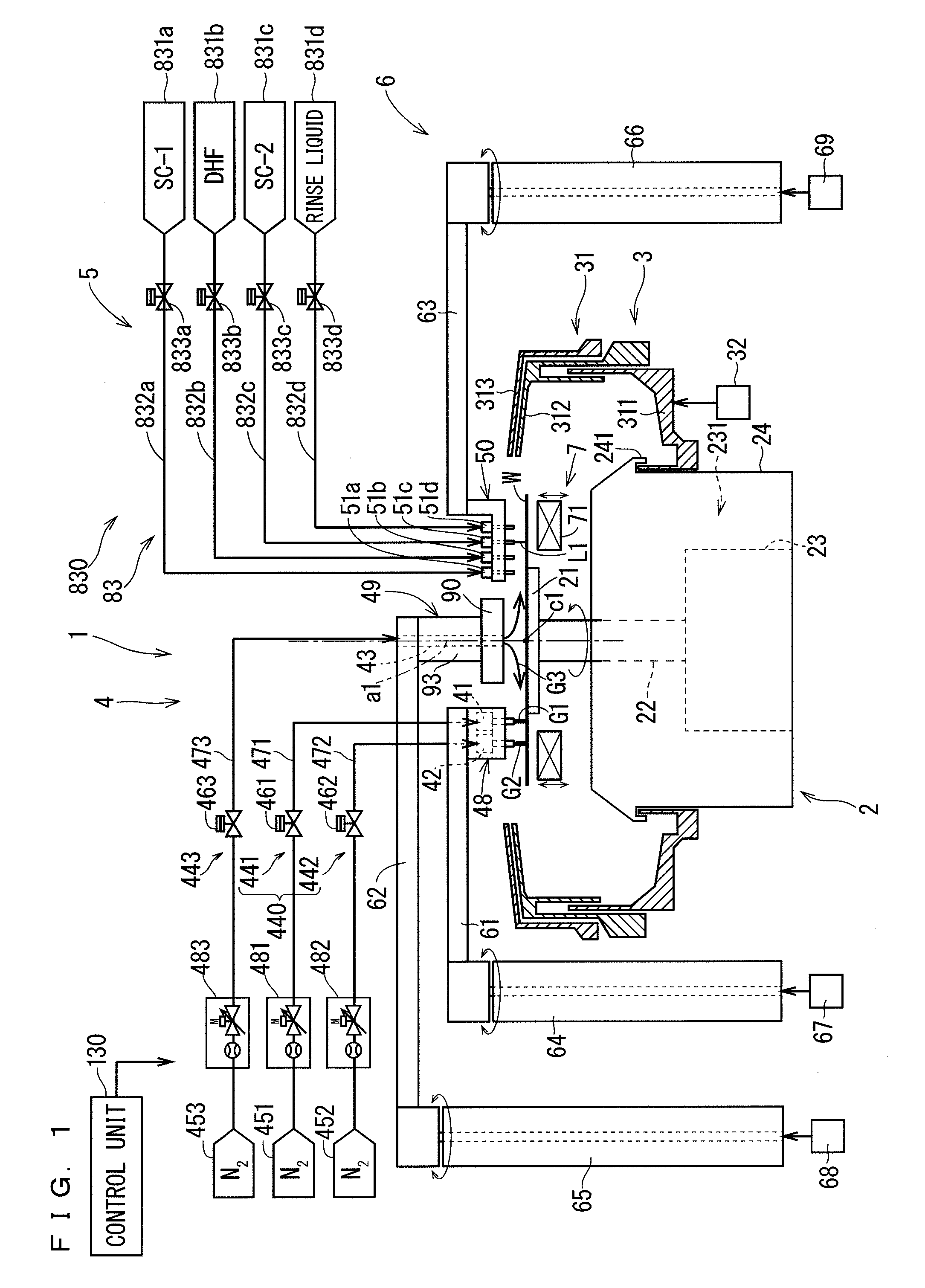
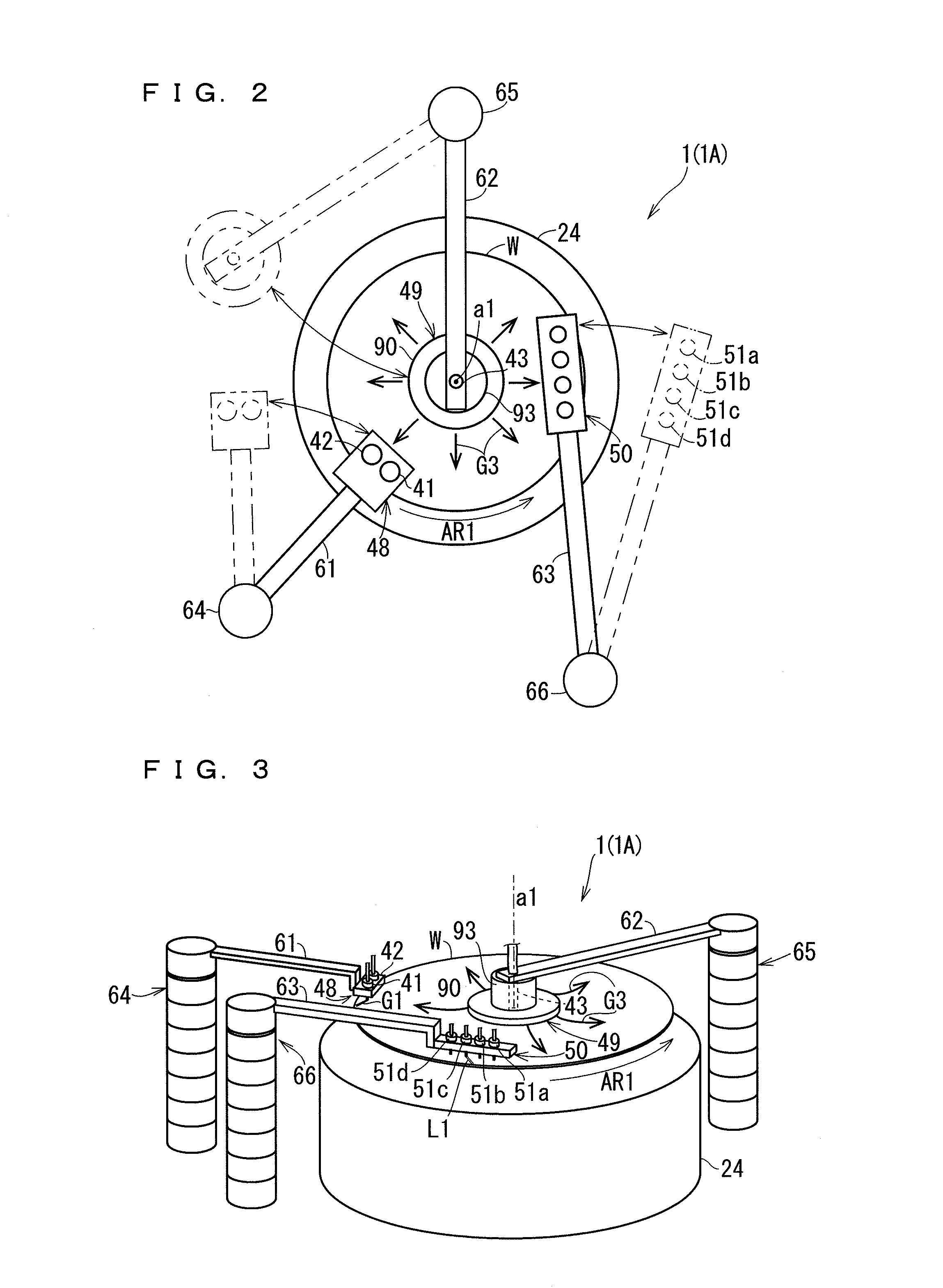
[0059]The configuration of a substrate processing apparatus 1 will be described with reference to FIGS. 1 to 4. FIGS. 1 to 3 are views for explaining the configuration of the substrate processing apparatus 1 according to an embodiment. FIGS. 1 and 2 are a schematic side view and a schematic top view, respectively, of the substrate processing apparatus 1. FIG. 3 is a schematic perspective view of the substrate processing apparatus 1 as viewed from diagonally above. FIG. 4 is a schematic top view of a substrate W, which illustrates an example of a positional relationship among positions at which a liquid flow of a processing liquid and gas flows of an inert gas that are discharged from the substrate processing apparatus 1 come into contact with the periphery of the substrate W.

[0060]FIGS. 1 to 3 illustrate the state in which the substrate W is being rotated in a predetermined direction of rotation (the dire...

second embodiment

2. Second Embodiment

[0171]2-1. Configuration of Substrate Processing Apparatus 1A

[0172]The configuration of a substrate processing apparatus 1A will be described with reference to FIGS. 2 to 4 and 14. FIGS. 14, 2, and 3 are views for explaining the configuration of the substrate processing apparatus 1A according to an embodiment. FIGS. 14 and 2 are a schematic side view and a schematic top view, respectively, of the substrate processing apparatus 1A. FIG. 3 is a schematic perspective view of the substrate processing apparatus 1A as viewed from diagonally above. FIG. 4 is a schematic top view of a substrate W illustrating an example of a positional relationship among positions at which a liquid flow of a processing liquid and gas flows of an inert gas that are discharged from the substrate processing apparatus 1A come into contact with the peripheral portion of the substrate W.

[0173]FIGS. 14, 2, and 3 illustrate a state in which the substrate W is being rotated in a predetermined dir...

third embodiment

3. Third Embodiment

[0239]3-1. Configuration of Substrate Processing Apparatus 1B

[0240]The configuration of a substrate processing apparatus 1B will be described with reference to FIGS. 23 to 27. FIGS. 23 to 25 are views for explaining the configuration of the substrate processing apparatus 1B according to an embodiment. FIGS. 23 and 24 are a schematic side view and a schematic top view, respectively, of the substrate processing apparatus 1B. FIG. 25 is a schematic perspective view of the substrate processing apparatus 1B as viewed from diagonally above. FIGS. 26 and 27 are a schematic top view and a schematic side view, respectively, of a substrate W, which illustrate an example of a positional relationship of the positions at which a liquid flow of a processing liquid and gas flows of an inert gas that are discharged from the substrate processing apparatus 1B come into contact with the peripheral portion of the substrate W. FIG. 26 is a top view schematically illustrating positions...


PUM


Abstract

A substrate processing apparatus includes a substrate holder, a rotating mechanism, a processing liquid discharge unit, and a gas discharge unit. The processing liquid discharge unit discharges a liquid flow of a processing liquid such that the liquid flow comes into contact with a landing position in a rotation path of a peripheral portion of an upper surface of the substrate being rotated. The gas discharge unit discharges a first gas flow of an inert gas from above toward a first position upstream from the landing position in a direction of rotation of the substrate in the rotation path, and discharges a second gas flow of the inert gas from above toward a second position upstream from the first position in the direction of rotation of the substrate in the rotation path. The kinetic energy of the second gas flow is lower than the kinetic energy of the first gas flow.

Description

BACKGROUND OF THE INVENTION[0001]Field of the Invention[0002]The present invention relates to a technique of processing substrates such as a semiconductor wafer, a glass substrate for liquid crystal display, a glass substrate for plasma display, a substrate for optical disc, a substrate for magnetic disk, a substrate for magneto-optical disk, a glass substrate for photomask, and a substrate for solar cell (hereinafter, merely referred to as “substrates”).[0003]Description of the Background Art[0004]A device pattern (circuit pattern) is not usually formed right up to the end face of a substrate, and in many cases, the device pattern is formed in the upper surface region located inside from the end face of the substrate by a constant width.[0005]In the deposition step for forming a device pattern, however, a film may be formed up to the outside of the region in which a device pattern is formed (hereinafter, merely referred to as a “device region”). The film formed outside of the devic...

Claims


Application Information

Patent Timeline
IPC IPC(8): H01L21/67H01L21/687
CPCH01L21/6708H01L21/67109H01L21/68764H01L21/02087H01L21/67017H01L21/68792H01L21/02052H01L21/02307H01L21/67051H01L21/67098H01L21/67126H01L21/6715H01L21/683
Inventor TAKEAKI, REIANDO, KOJIMAEGAWA, TADASHIYASUTAKE, YOSUKE
Owner DAINIPPON SCREEN MTG CO LTD
Why Eureka
Try Eureka