Chemical reaction cleaning pond for chemical cleaning machine of vehicle condenser

A chemical cleaning and condenser technology, applied in the field of mechanical automation, can solve the problems of slow cleaning speed, oil residue, poor cleaning effect, etc., and achieve the effect of improving cleaning efficiency and preventing damage

Active Publication Date: 2015-05-27
江苏懿能达制冷设备有限公司
8 Cites 0 Cited by

AI-Extracted Technical Summary

Problems solved by technology

[0002] Cars play a very important role in the current life and work. In order to improve the comfort of the car, the current car, whether it is a truck or a car, is equipped with a car air conditioner. The condenser is a part of the car air conditioner. The machine used in the production of the condenser needs to lubrica...

Abstract

The invention discloses a chemical reaction cleaning pond for a chemical cleaning machine of a vehicle condenser. The chemical reaction cleaning pond for the chemical cleaning machine of the vehicle condenser comprises a liquid storage tank, a water inlet device, a chemical agent conveying device, a servo feeding and shifting manipulator and a frame type bracket, wherein the water inlet device and the chemical agent conveying device are arranged on the front and back sides of the liquid storage tank respectively; the frame type bracket fixed on the plant ground is arranged above the liquid storage tank; the servo feeding and shifting manipulator is arranged on the frame type bracket. Through the way, the vehicle condenser can be chemically cleaned effectively, oil stains in a pipe are removed, harm to the respiratory tracts of workers caused by a chemical cleaning agent is prevented, and the cleaning efficiency is increased.

Application Domain

Technology Topic

Image

  • Chemical reaction cleaning pond for chemical cleaning machine of vehicle condenser
  • Chemical reaction cleaning pond for chemical cleaning machine of vehicle condenser
  • Chemical reaction cleaning pond for chemical cleaning machine of vehicle condenser

Examples

  • Experimental program(1)

Example Embodiment

[0013] The preferred embodiments of the present invention will be described in detail below with reference to the accompanying drawings, so that the advantages and features of the present invention can be more easily understood by those skilled in the art, and the protection scope of the present invention can be more clearly defined.
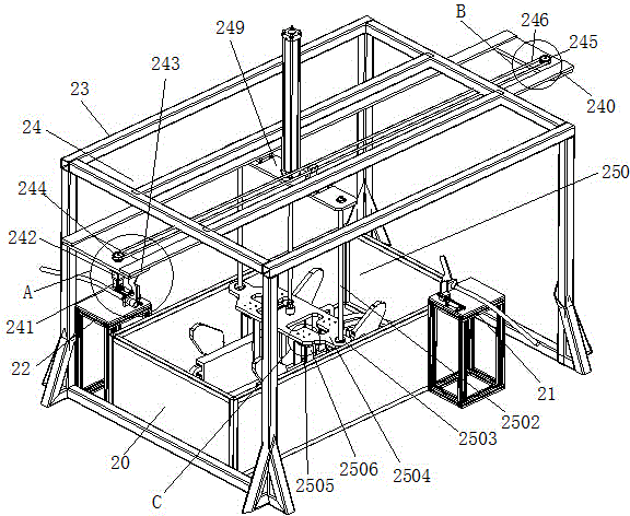
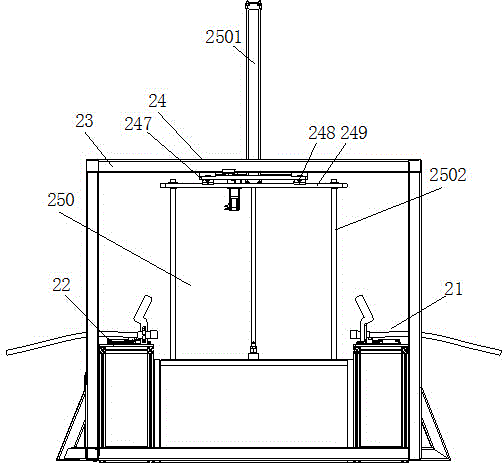
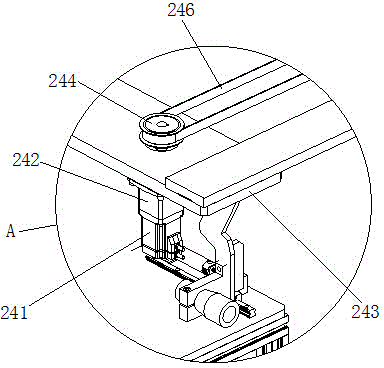
[0014] see Figure 1 to Figure 5 , the embodiments of the present invention include:
[0015] A chemical reaction cleaning tank of a vehicle condenser chemical cleaning machine, the chemical reaction cleaning tank of the vehicle condenser chemical cleaning machine includes a liquid storage tank 20, a water inlet device 21, a chemical agent conveying device 23, and a servo feeding and transferring manipulator. 24 and a frame-type bracket 23, the front and rear sides of the liquid storage tank 20 are respectively provided with a water inlet device 21 and a chemical agent delivery device 22, and a frame-type bracket 23 fixed on the factory floor is arranged above the liquid storage tank 20. A servo feeding and transferring manipulator 24 is installed on the bracket 23;
[0016] The servo feeding and transferring manipulator 24 includes a servo conveyor 240, a servo motor 241, a reducer 242, a reducer flange 243, a first reducer pulley 244, a first follower pulley 245, an anti-corrosion synchronous belt 246, A linear slide rail 247, a first linear slider 248, a servo conveying plate 249 and a lifting and grabbing mechanism 250. The servo conveying frame 240 is a rectangular frame, and the bottom surface of the servo conveying frame 240 is provided with two parallel first A linear slide rail 247, the first linear slide rail 247 is provided with two first linear slide blocks 248, the first linear slide blocks 248 are fixed on the servo conveying plate 249, and the two sides of the servo conveying plate 249 The two ends of the anti-corrosion synchronous belt 246 are respectively connected. The anti-corrosion synchronous belt 246 is sleeved on the first reducer pulley 244 and the first follower pulley 245. The first reducer pulley 244 is installed on the reducer 242. The reducer 242 Installed on the reducer flange plate 243, the reducer flange plate 243 is fixed on the left side of the servo conveyor 240, the input end of the reducer 242 is also connected with a servo motor 241, and the first follower pulley 245 is installed on the servo conveyor 240 On the right side of the servo conveyor plate 249, a lifting and grabbing mechanism 250 is also installed;
[0017] The lifting and grabbing mechanism 250 includes a lifting cylinder 2501, a linear guide post 2502, a flanged linear bearing 2503, a lifting plate 2504, a waterproof pneumatic flat clamping cylinder 2505 and a clamping arm 2506. The lifting cylinder 2501 is installed on the servo conveying plate 249 , the piston rod of the lift cylinder 2501 is connected to the upper plane of the lift plate 2504, the two ends of the lift plate 2504 are provided with a flanged linear bearing 2503, and the flanged linear bearing 2503 is inserted with a linear guide column that can move up and down 2502, the upper end of the linear guide post 2502 is fixed on the servo conveying plate 249, and the lower plane of the lifting plate 2504 is provided with four waterproof pneumatic flat clamp cylinders 2505 that operate synchronously, and two clamp arms 2506 are installed on each waterproof pneumatic flat clamp cylinder 2505. , the two clamp arms 2506 installed on the same waterproof pneumatic flat clamp cylinder 2505 are opposite in position.
[0018] The chemical reaction cleaning pool of the vehicle condenser chemical cleaning machine of the invention can effectively chemically clean the vehicle condenser, remove oil stains in the pipes, prevent chemical cleaning agents from causing damage to the respiratory tract of workers, and improve cleaning efficiency.
[0019] The above descriptions are only the embodiments of the present invention, and are not intended to limit the scope of the present invention. Any equivalent structure or equivalent process transformation made by using the contents of the description and drawings of the present invention, or directly or indirectly applied to other related technologies Fields are similarly included in the scope of patent protection of the present invention.

PUM

no PUM

Description & Claims & Application Information

We can also present the details of the Description, Claims and Application information to help users get a comprehensive understanding of the technical details of the patent, such as background art, summary of invention, brief description of drawings, description of embodiments, and other original content. On the other hand, users can also determine the specific scope of protection of the technology through the list of claims; as well as understand the changes in the life cycle of the technology with the presentation of the patent timeline. Login to view more.

Similar technology patents

Rubber-plastic mining air duct with reflective effect

InactiveCN107246278AEasy to walkAvoid causing harmTunnel/mines ventillationEngineeringTextile
Owner:阜宁县曙光合成革有限公司

Safety protection device of lifting belt or traction belt and use method of safety protection device

PendingCN113401783AAvoid causing harmBelt fasteningsSafety gearAutomotive engineeringTraction belt
Owner:CHINA THIRD METALLURGICAL GRP

Earthquake rescue equipment with life detection function

InactiveCN111976852AEasy rescueAvoid causing harmEndless track vehiclesGeological measurementsSprocketMarine engineering
Owner:象山奋凡消防科技有限公司

Building fire-fighting robot

PendingCN111228701AAvoid causing harmFire rescueWater pipeWater storage tank
Owner:IANGSU COLLEGE OF ENG & TECH

Biosafety cabinet with external scanning equipment

PendingCN111957357AAvoid causing harmImprove operational convenienceEnclosures/chambersSurveillance cameraStructural engineering
Owner:上海上净净化设备有限公司

Classification and recommendation of technical efficacy words

  • Improve cleaning efficiency
  • Avoid causing harm

Method for measuring and acquiring body image data of dairy cow

ActiveCN101904748AAvoid stress responseAvoid causing harmPhotogrammetry/videogrammetryPerson identificationBody imagesComputer processing
Owner:SHANGHAI INSTR RES INST

Cutting device for sheet metal processing

PendingCN110842380AAvoid causing harmEliminate fire hazardsLaser beam welding apparatusWater circulationFire hazard
Owner:苏州市金典精密制造有限公司

Child tricycle and front wheel thereof

InactiveCN106005237AAvoid causing harmChildren cyclesVehicle transmissionClutchThree-wheeled car
Owner:KUNSHAN LITTLE DINASAUR CHILD PROD
Why Eureka
Try Eureka