Protective element with heat energy guiding function

A technology for protecting components and thermal energy, applied in resistor cooling/heating/ventilation devices, resistor shells/packaging shells/potting, varistors, etc.

Inactive Publication Date: 2013-07-03
陈奎彰
View PDF5 Cites 0 Cited by
  • Summary
  • Abstract
  • Description
  • Claims
  • Application Information

AI Technical Summary

Problems solved by technology

When the two ends of the varistor receive continuous voltage, it will cause gradual aging, which will cause the varistor to heat slowly and destroy the grain boundary structure of the varistor, resulting in failure. In addition, the large current and large energy generated by the instantaneous surge attack, exceeding the tolerance limit of the varistor, resulting in fire or burst
[0003] In order to avoid the harm caused by the failure of the varistor, a thermal fuse is generally used for protection. The thermal fuse is generally triggered by a low melting point alloy. This method requires an excellent contact between the varistor and the thermal fuse to function in time. However, most failures of varistors are unpredictable, so there is not enough time to transfer heat energy to the thermal fuse, and the varistor cannot be effectively protected. Therefore, a composite component that is closely bonded to the varistor and the thermal fuse has been developed. For example, thermally protected metal oxide varistor (TMOV, Thermal Metal Oxide Varistor), please refer to Figure 1, which is a schematic diagram of an existing thermally protected metal oxide varistor 1, the principle of which is to combine the varistor 2 and the thermal fuse 3 are closely attached to facilitate heat conduction to the low-melting point alloy metal of the thermal fuse. Please refer to Fig. 2 and Fig. 3, which are schematic diagrams of the existing thermal fuse 3 before and after

Method used


Image

  • Protective element with heat energy guiding function
  • Protective element with heat energy guiding function
  • Protective element with heat energy guiding function

Examples


Embodiment Construction

[0042] The present invention will be further described below in conjunction with the accompanying drawings and specific embodiments, so that those skilled in the art can better understand the present invention and implement it, but the examples given are not intended to limit the present invention.

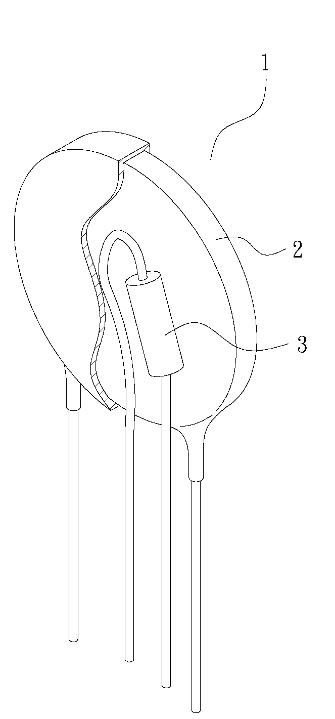
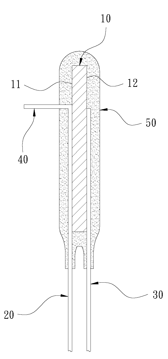
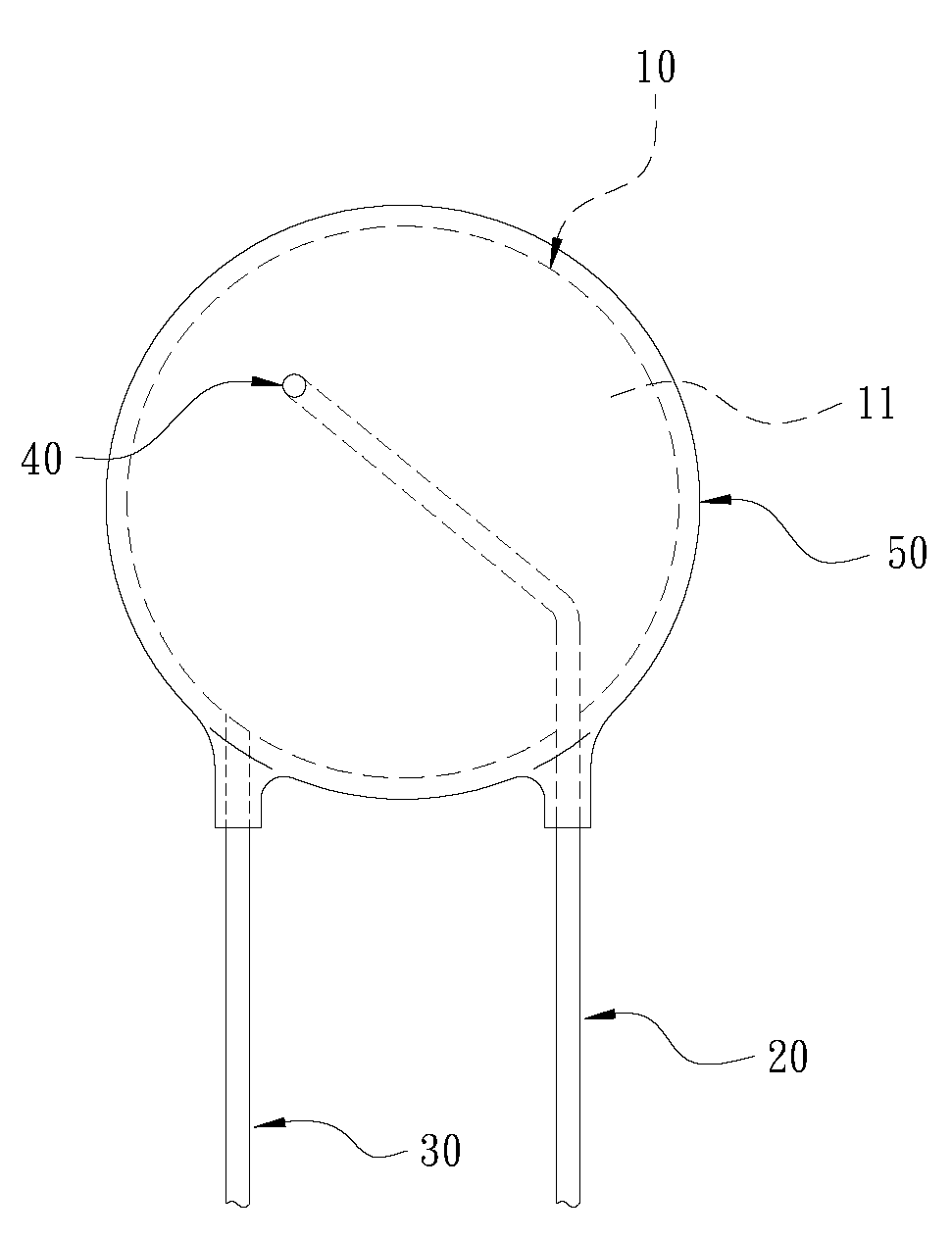
[0043] Please refer to Fig. 4, Fig. 5 and shown in Fig. 6 at the same time, it is the structural representation, the front view and the back view of the first preferred embodiment of the present invention, and it mainly consists of a body 10, a first lead-out electrode 20, a second The lead electrode 30, a thermal energy guiding part 40 and a packaging material 50 are composed; wherein:

[0044] The main body 10, in this embodiment, the main body 10 is a varistor substrate, which is a prior art, so it is not intended to be described in detail.

[0045] The first lead-out electrode 20 is electrically connected to the first surface 11 of the body 10 . In this embodiment, the first l...


PUM


Abstract

The invention discloses a protective element with a heat energy guiding function. The element comprises a main body which is electrically connected with a first lead electrode and a second lead electrode. The main body is coated by using a packaging material. A heat energy guiding part is arranged on the main body. The heat energy guiding part is a continuous lead wire with one end arranged on the first lead electrode and the other end extending outwards and penetrating to the outer side of the packaging material. With the structure, with the heat energy guiding part, hear energy can be conducted into or out of the main body with a thermal conduction manner. Therefore, the failure of timely perception when electronic components fail due to overloading can be avoided, and harm can be prevented.

Description

technical field [0001] The invention relates to a protection element of an electronic product, in particular to a protection element capable of conducting heat energy correctly and rapidly. Background technique [0002] There are many types of passive protection components for electronic products, such as varistors (VDR, Voltage Dependent Resistor) or thermal fuses (TCO, Thermal Cut-Off), etc. Among them, varistors are a kind of transient overvoltage protection resistors. A common varistor is a metal oxide varistor (MOV, Metal Oxide Varistor). Its protection mode is that when the power supply voltage is normal, the varistor is in high impedance mode. When the power supply generates abnormal high voltage, the varistor will Quickly switch to low-impedance mode, let the surge current pass, and use heat to eliminate abnormal energy, thus protecting fragile electronic components or circuits. When the two ends of the varistor receive continuous voltage, it will cause gradual agin...

Claims


Application Information

Patent Timeline
IPC IPC(8): H01C7/10H01C1/02H01C1/08
Inventor 陈奎彰
Owner 陈奎彰
Why Eureka
Try Eureka