

Building fire-fighting robot
A fire-fighting robot, robot technology, applied in fire rescue and other directions, can solve problems such as personal injury, and achieve the effect of avoiding injury
- Summary
- Abstract
- Description
- Claims
- Application Information
AI Technical Summary
Problems solved by technology
Method used
Image

Examples
Embodiment
[0039] The following is attached Figure 1-6 The present invention is described in further detail.
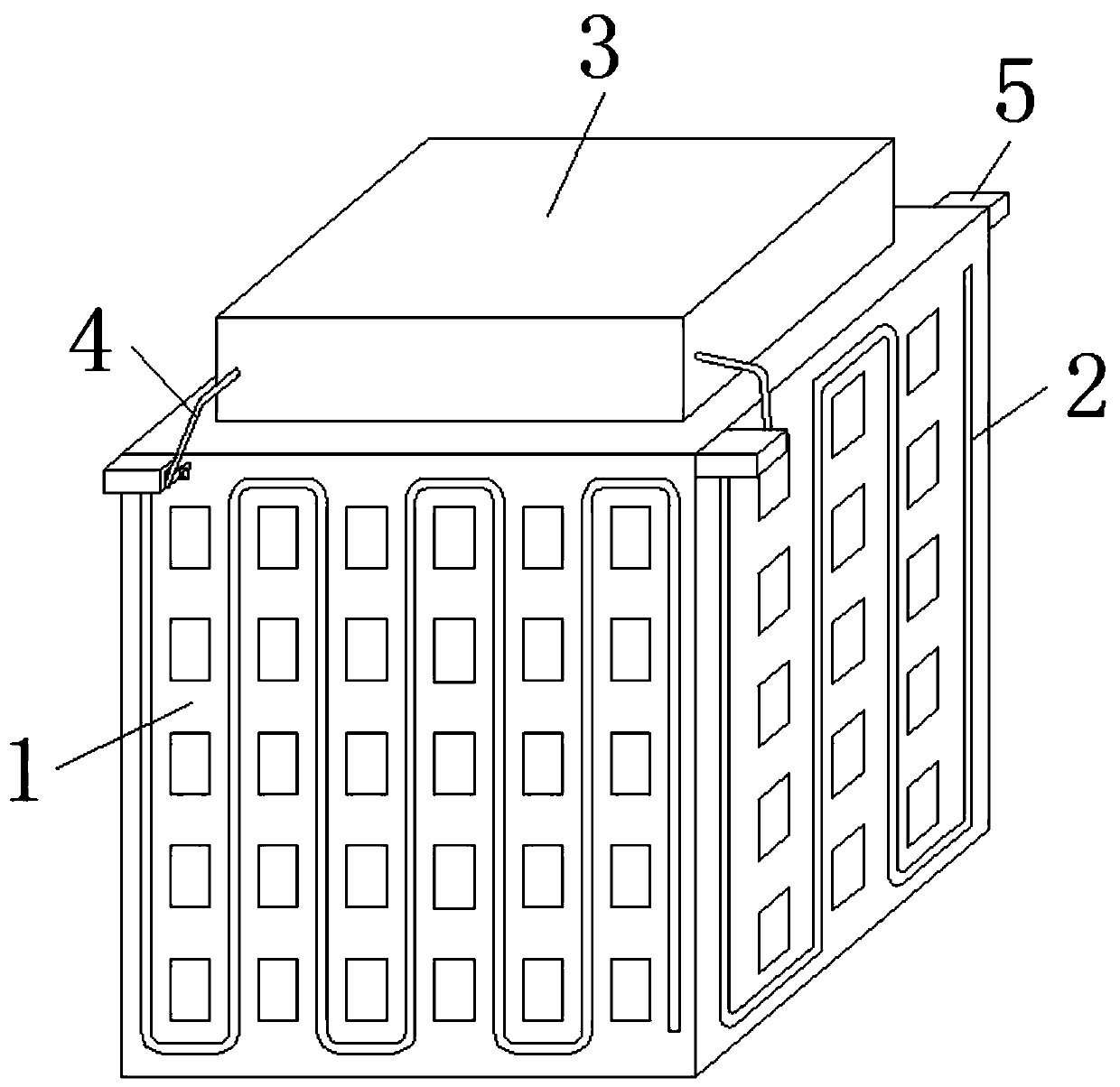
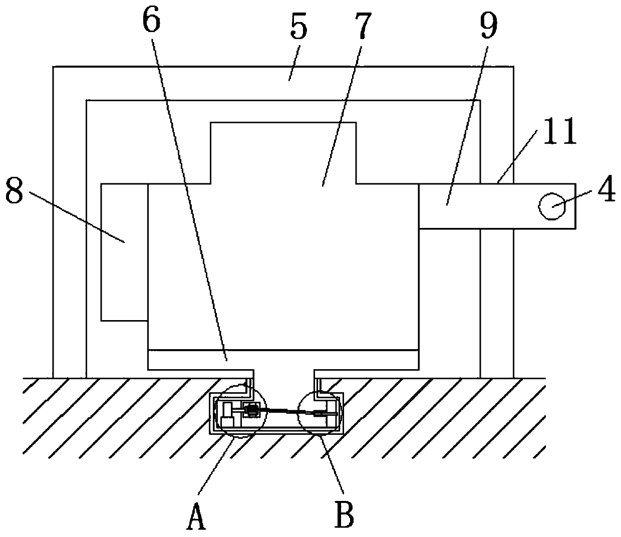
[0040] A building house fire fighting robot, such as figure 1 As shown, including the house main body 1, the surrounding surface of the house main body 1 is provided with stroke grooves 2, the top of the house main body 1 is fixedly connected with a water storage tank 3, and the surrounding surfaces of the water storage tank 3 are fixedly connected with a fire water pipe 4, and the house main body 1 The surface around the top of the top is fixedly connected with a protective frame 5, and the inner wall of the stroke groove 2 is provided with a moving device, and the moving device includes a robot mounting block 6;
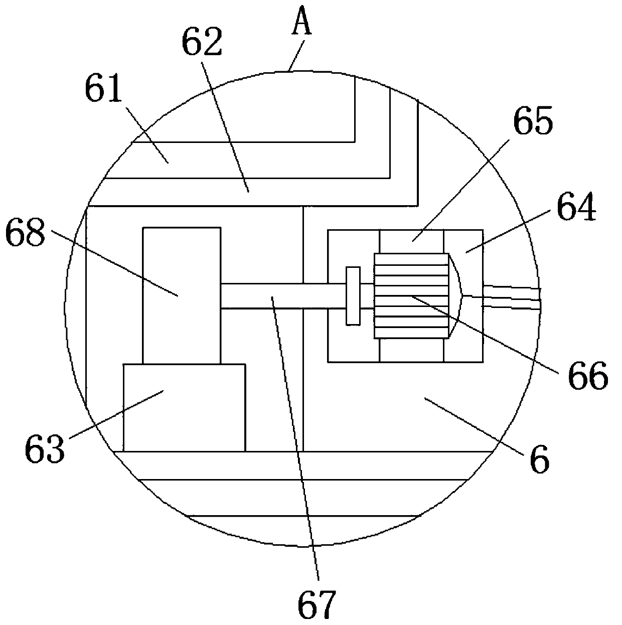
[0041] Such as image 3 and Figure 6 As shown, the inner wall of the travel groove 2 is fixedly connected with an insulating pad 61, and the surface of the insulating pad 61 is fixedly connected with a travel track 62. The power supply of the main body 1 is ele...
PUM
 Abstract
Description
Claims
Application Information