
Airplane control plane deflection angle measuring system

A measurement system and declination technology, applied in the field of aircraft rudder surface declination measurement system, can solve problems such as difficulty in designing a fixture, lack of versatility, complex system composition, etc., and achieve convenient layout, small space size, and test accuracy. high effect

Inactive Publication Date: 2015-05-27
XIAN AIRCRAFT DESIGN INST OF AVIATION IND OF CHINA
View PDF5 Cites 18 Cited by
  • Summary
  • Abstract
  • Description
  • Claims
  • Application Information

AI Technical Summary

Problems solved by technology

[0005] (1) Using angular displacement sensors, equipped with special signal conditioners and test recording equipment, the system composition is complex, resulting in high costs;
[0006] (2) Many signal transmission lines and power lines are used between sensors, signal conditioners and test recording equipment, which is inconvenient to use;
[0007] (3) For the specific actuation control surface and its installation space, the design of special transmission connectors and sensor installation fixtures is developed and produced for specific requirements and is not universal. After the specific requirements change, it needs to be adapted Sexual changes, even reprocessing, production;
[0008] (4) For many actuating control surfaces with different installations and movements, it is difficult to design a universal fixture, and the special transmission connector and installation fixture need to have a corresponding installation space, which is inconvenient to use

Method used


Image

  • Airplane control plane deflection angle measuring system
  • Airplane control plane deflection angle measuring system
  • Airplane control plane deflection angle measuring system

Examples


Embodiment Construction

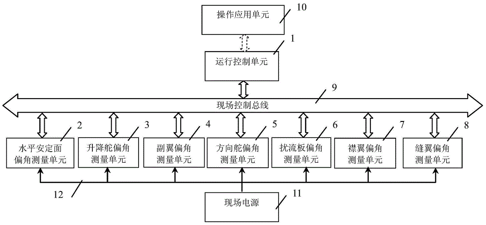
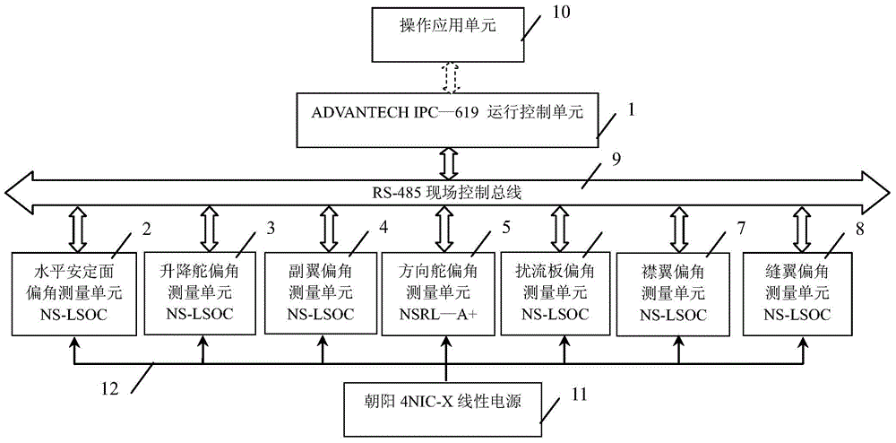
[0039] The composition structure of an aircraft rudder deflection angle measurement system is as follows: figure 1 As shown, it consists of operation control unit 1, horizontal stabilizer deflection angle measurement unit 2, elevator deflection angle measurement unit 3, aileron deflection angle measurement unit 4, rudder deflection angle measurement unit 5, spoiler deflection angle measurement unit 6, flap Wing deflection angle measurement unit 7, slat deflection angle measurement unit 8, field control bus 9, operation application unit 10, field power supply 11, power line 12 are composed, and the operation control unit 1 and each control surface deflection angle measurement unit are equipped with capable The independently operated controller and the field data bus communication interface, the operation control unit 1, and the rudder surface deflection angle measurement units realize interconnection and communication through the field data bus 9, and carry out the transmission ...


PUM


Abstract

The invention discloses an airplane control plane deflection angle measuring system, and belongs to the technical field of engineering observation and control. The airplane control plane deflection angle measuring system is characterized by comprising an operation control unit [1], a horizontal stabilizer deflection angle measuring unit [2], an elevator deflection angle measuring unit [3], an aileron deflection angle measuring unit [4], a rudder deflection angle measuring unit [5], a spoiler deflection angle measuring unit [6], a flap deflection angle measuring unit [7], a slat deflection angle measuring unit [8], a field control bus [9], an operation application unit [10], a field power supply [11] and a field power line [12], wherein the operation control unit [1] executes the order of the operation application unit [10], and realizes transmission of control orders, state information and measurement data with the deflection angle measuring units through the field control bus [9]; the field power supply [11] supplies power to the various deflection angle measuring units through the power line [12]. The airplane control plane deflection angle measuring system disclosed by the invention is complete in functions, reasonable and compact in structure, reliable in working, convenient to use, and good in expandability and clipping modularity.

Description

Technical field [0001] The invention relates to an aircraft rudder surface deflection angle measurement system, in particular to a measurement sensor with a field data bus interface to realize the aircraft rudder surface deflection angle measurement system and a method thereof, and belongs to the technical field of engineering test and measurement and control. Background technique [0002] Aircraft, as an important means of transportation in modern times, is more and more popular with people because of its fastness and safety, and has been closely related to people's life and work. The flight of an aircraft is inseparable from the flight control system. The pilot uses the flight control system to control the aircraft's horizontal stabilizer, elevator, aileron, rudder, spoiler, flaps and slats and other rudder surfaces to realize the control of the aircraft flight. Attitude control, thereby changing the position and trajectory of the aircraft to complete different flight task...

Claims


Application Information

Patent Timeline
Patent Type & Authority Applications(China)
IPC IPC(8): G01B21/22
CPCG01B21/22
Inventor 支超有安刚李霞
Owner XIAN AIRCRAFT DESIGN INST OF AVIATION IND OF CHINA
Learn More