

A device for measuring the temperature of a fuse in a capacitor
Patent Information
- Authority / Receiving Office
- CN · China
- Patent Type
- Patents(China)
- Current Assignee / Owner
- STATE GRID CORP OF CHINA
- Publication Date
- 2018-08-14
Smart Images
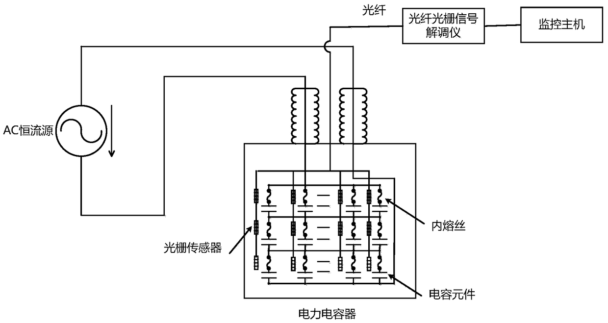
Figure 1 
Figure 2 
Figure 3
Abstract
Description
technical field
[0001] The invention relates to a capacitor temperature measuring device, in particular to a capacitor internal fuse temperature measuring device. Background technique
[0002] Power capacitors are mainly used for reactive power compensation of power systems to improve power factor. In order to make it operate more reliably, the current industry mainly considers connecting internal fuses in series with the internal components of the capacitor. When the capacitor fails completely due to dielectric weakness, the internal fuse connected in series with the component will act, so that only a part of the damaged component is isolated, and the capacitor will continue to operate with only a slight power reduction. At this time, the disturbance in the capacitor bank can be ignored, and the total capacity of the capacitor bank will not be significantly affected by the action of a fuse. The introduction of the internal fuse protects the capacitor elements, but virtuall...