A micro-current detection device for single-molecule conductance measurement system
A conductance measurement and detection device technology, applied to measuring devices, using digital measurement technology to measure, changing range circuits, etc., can solve problems such as conductance changes, and achieve good linearity, high sensitivity, and large dynamic range.
- Summary
- Abstract
- Description
- Claims
- Application Information
AI Technical Summary
Problems solved by technology
Method used
Image
Examples
Embodiment 1
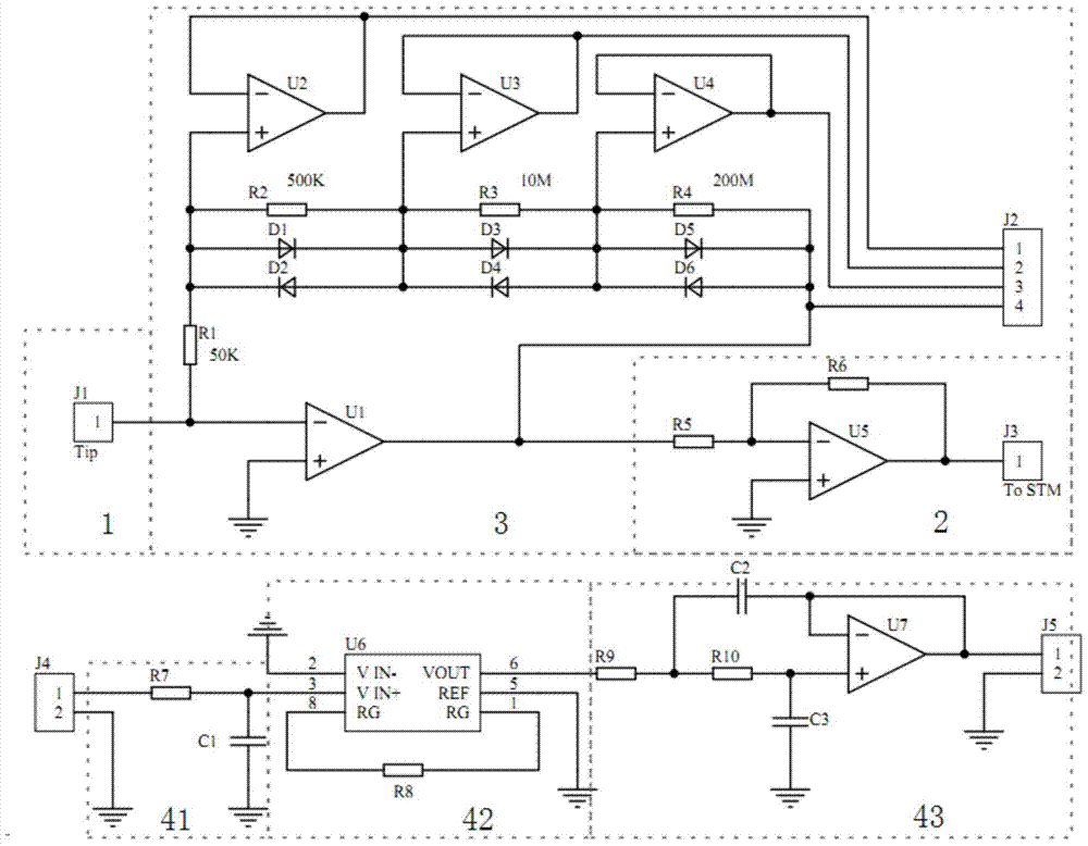
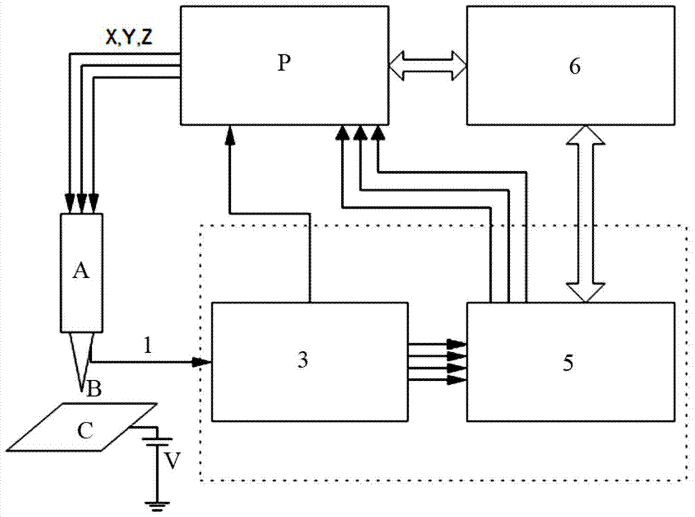
[0033] Take a piece of gold wire, cut it mechanically to make tip B, and assemble it into the scanning head with four-channel microcurrent amplifier; use Au(111) single crystal electrode as substrate C, soak substrate C in 1mM 4, The self-assembled film was formed in 4'-bipyridyl aqueous solution for 5 minutes, and then placed in the aqueous solution for 5 minutes to wash away excess molecules, dried and placed in the sample stage. First drive the motor so that the needle tip approaches the Au(111) substrate. After reaching the tunnel current region, the motor stops working. At this time, the piezoelectric ceramic tube of the scanning head starts to work. By changing the x, y and z directions added to the piezoelectric ceramic A The voltage can drive the tip B to move in three directions of x, y and z. When the mechanical and thermal drift of the whole device is almost negligible, keep the needle tip B and the substrate C at a bias voltage of 200mV (denoted as V), drive the ne...
Embodiment 2
[0035] Take a piece of gold wire, cut it mechanically to make a needle tip, and assemble it into a scanning head containing a four-channel microcurrent amplifier; use Au(111) single crystal electrode as the substrate, soak the substrate in 1mM 1,2-di The self-assembled film was formed in an aqueous solution of (4-pyridyl)ethylene for 5 minutes, and then soaked in an aqueous solution for 5 minutes to wash off excess molecules, and then put it into the sample stage after drying. First drive the motor so that the needle tip approaches the Au(111) substrate. After reaching the tunnel current region, the motor stops working. At this time, the piezoelectric ceramic tube of the scanning head starts to work. By changing the voltage applied to the piezoelectric ceramic in the x, y and z directions , which can drive the needle tip to move in the x, y and z directions. When the mechanical and thermal drift of the whole device is almost negligible, keep the needle tip and the substrate at...
PUM
 Abstract
Description
Claims
Application Information
 - R&D
- Intellectual Property
- Life Sciences
- Materials
- Tech Scout
- Unparalleled Data Quality
- Higher Quality Content
- 60% Fewer Hallucinations
Browse by: Latest US Patents, China's latest patents, Technical Efficacy Thesaurus, Application Domain, Technology Topic, Popular Technical Reports.
© 2025 PatSnap. All rights reserved.Legal|Privacy policy|Modern Slavery Act Transparency Statement|Sitemap|About US| Contact US: help@patsnap.com


