Sonar sensor
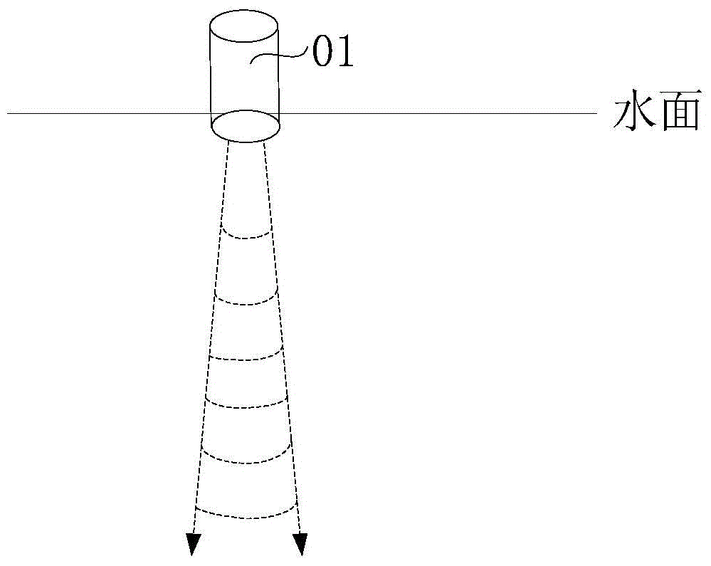
A sensor and sonar technology, which is applied in the field of sonar sensors, can solve the problems of narrow emission angle of the acoustic wave transmitter, low detection ability, and inability to obtain the spatial distribution of fish schools, etc., to achieve the effect of improving practicability and detection efficiency
- Summary
- Abstract
- Description
- Claims
- Application Information
AI Technical Summary
Problems solved by technology
Method used
Image
Examples
Embodiment 1
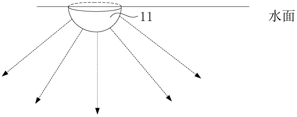
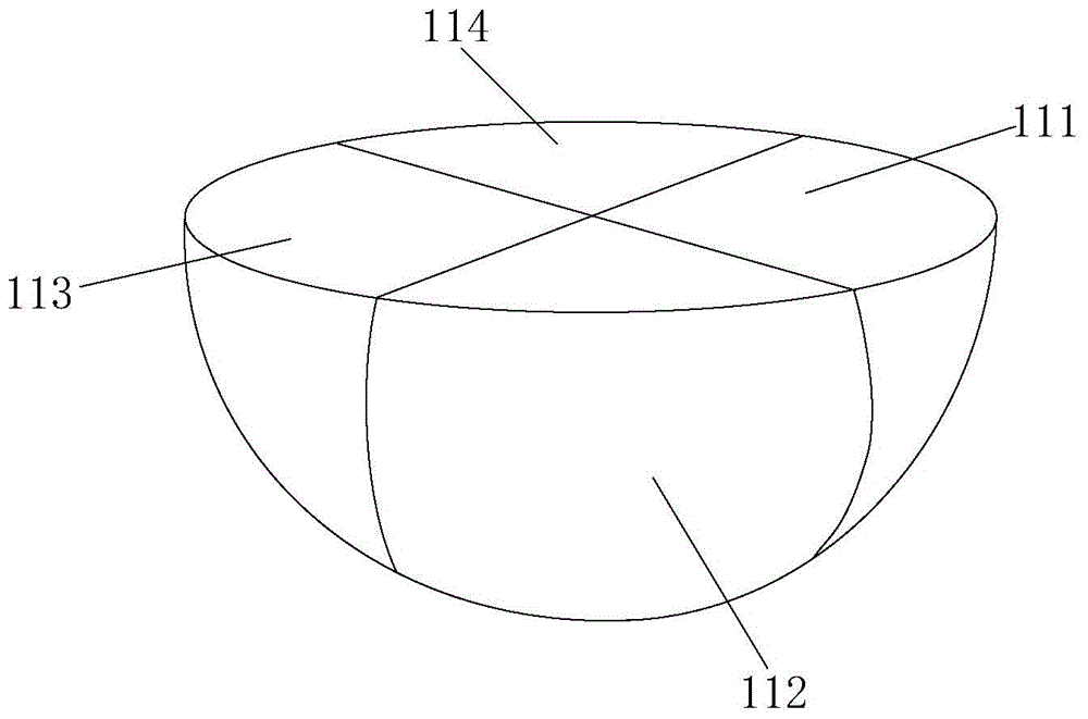
[0036] figure 2 is a schematic side view of the sonar sensor provided in Embodiment 1 of the present invention, Figure 3a It is a schematic side view of the multi-unit sonar sensor provided in Embodiment 1 of the present invention, Figure 3b It is a schematic bottom view of the multi-unit sonar sensor provided in Embodiment 1 of the present invention. Such as figure 2 As shown, the sonar sensor may include a sonar sensing unit 11, the sonar sensing unit 11 is used to emit a sound wave signal, and receive the sound wave signal reflected by the fish school, and measure the position and / or position of the fish school according to the received sound wave signal Or the direction of the school of fish relative to the sonar sensor.
[0037] Specifically, the sonar sensing unit 11 can measure the position of the school of fish or the direction of the school of fish relative to the sonar sensor according to the received acoustic wave signal; it can also measure the position of t...
Embodiment 2
[0052] Figure 4 is a schematic side view of the sonar sensor provided in Embodiment 2 of the present invention, Figure 5 It is a schematic bottom view of the multi-unit sonar sensor provided in Embodiment 2 of the present invention. Such as Figure 4 As shown, the sonar sensor may include a sonar sensing unit 21, and the sonar sensing unit 21 is used to emit sound wave signals and receive sound wave signals reflected by fish schools.
[0053] Wherein, the sonar sensor is submerged in water, the shape of the sonar sensing unit 21 is cylindrical, and is connected with the connection line 22, and the depth of the sonar sensor in the water is controlled by the connection line 22, wherein, the The sonar sensing unit 21 is used to emit sound wave signals in a direction perpendicular to the side of the cylindrical sonar sensing unit, and receive the sound wave signals reflected by the fish school, and measure the distance between the fish school and the sonar sensor according to ...
Embodiment 3
[0061] Image 6 It is a schematic bottom view of the phased array sonar sensor provided in Embodiment 3 of the present invention, Figure 7a It is a schematic diagram of the phased array sonar sensor emitting the acoustic wave signal provided in the third embodiment of the present invention, Figure 7b It is a schematic diagram of the phased array sonar sensor receiving the acoustic wave signal provided in the third embodiment of the present invention. combine Image 6 , Figure 7a with Figure 7b , the phaser sonar sensor 31 includes
[0062] The phased array sonar sensor 31 floats on the water surface and includes multiple rows (or columns) of three-dimensional convex sonar sensing units 311 provided in Embodiment 1 of the present invention. The multi-row three-dimensional convex sonar sensing unit 311 is used to emit sound wave signals driven by scanning signals, and receive the sound wave signals reflected by fish schools. The acoustic wave signal received by the sen...
PUM
| Property | Measurement | Unit |
|---|---|---|
| Launch angle | aaaaa | aaaaa |
Abstract
Description
Claims
Application Information
 - R&D Engineer
- R&D Manager
- IP Professional
- Industry Leading Data Capabilities
- Powerful AI technology
- Patent DNA Extraction
Browse by: Latest US Patents, China's latest patents, Technical Efficacy Thesaurus, Application Domain, Technology Topic, Popular Technical Reports.
© 2024 PatSnap. All rights reserved.Legal|Privacy policy|Modern Slavery Act Transparency Statement|Sitemap|About US| Contact US: help@patsnap.com


