Temperature control circuit for an electrical heater.

A technology for temperature control and electric heaters, applied in the direction of temperature control using electric methods, can solve the problems of complex temperature control circuit structure, unstable working performance, inconvenient debugging, etc., and achieve easy production, stable working performance, and easy debugging convenient effect

Inactive Publication Date: 2015-05-27
SICHUAN DITEL ELECTRONICS
View PDF0 Cites 4 Cited by
  • Summary
  • Abstract
  • Description
  • Claims
  • Application Information

AI Technical Summary

Problems solved by technology

But the temperature control circuit structure of the existing electric heater is co...

Method used


Image

  • Temperature control circuit for an electrical heater.

Examples


Embodiment Construction

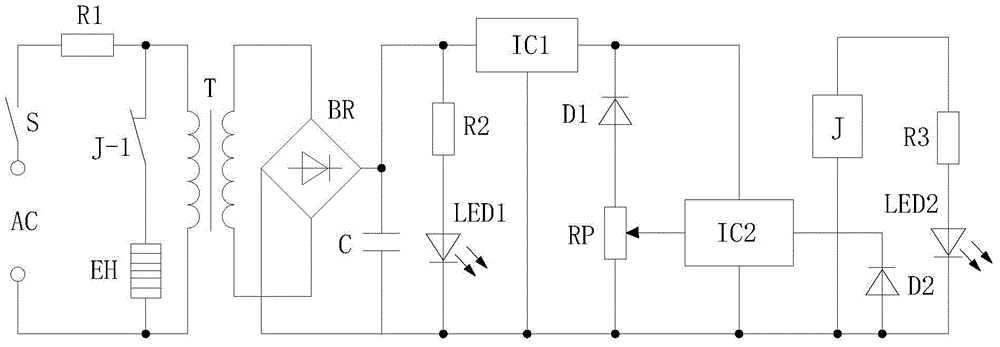
[0009] The present invention will be further described below in conjunction with accompanying drawing:

[0010] Such as figure 1 As shown, a temperature control circuit of an electric heater in the present invention includes an AC power supply AC, a switch S, a first resistor R1 to a third resistor R3, a transformer T, a first light-emitting diode LED1, a second light-emitting diode LED2, a bridge Rectifier BR, first diode D1, second diode D2, heater EH, capacitor C, relay J, potentiometer RP, three-terminal voltage regulator integrated chip IC1 and electronic switch integrated chip IC2, the first AC power supply AC One end is connected to the first end of the switch S, the second end of the switch S is connected to the first end of the first resistor R1, and the second end of the first resistor R1 is respectively connected to the normally closed contact switch J-1 of the relay J The first end is connected to the first end of the primary coil of the transformer T, the second ...


PUM


Abstract

The invention discloses a temperature control circuit for an electrical heater. The temperature control circuit comprises an alternating-current power source, a switch, a first resistor, a second resistor, a third resistor, a transformer, a first light-emitting diode, a second light-emitting diode, a bridge rectifier, a first diode, a second diode, a heater, a capacitor, a relay, a potentiometer, a three-terminal voltage stabilization integrated chip, and an electronic switch integrated chip. When the temperature is relatively low, the electronic switch integrated chip is cut off as the control pole voltage is lower than the trigger voltage, the relay is in a release state, a normally-closed contact switch is opened, and the heater heats an object; and when the temperature rises and surpasses a set temperature, an electronic switch in the electronic switch integrated chip is switched on as the control pole voltage reaches the trigger voltage, the relay is closed, the normally-closed contact switch is closed, and the heater stops heating. The temperature control circuit can control the temperature of the electrical heater within a set scope, and has advantages of simple circuit structure, easy manufacture, stable work performance, and convenient debugging.

Description

technical field [0001] The invention relates to a control circuit of an electric heater, in particular to a temperature control circuit of the electric heater. Background technique [0002] Electric heaters are heating equipment that uses electricity as energy for heating and heating. It can be widely used in residences, offices, hotels, shopping malls, hospitals, schools, train carriages and other places. It has strong radiation ability and wide radiation area. It mainly uses infrared radiation and heat The way of convection is used to send heat, the temperature can be adjusted, it is safe and convenient to use, and is widely favored by people. However, the temperature control circuit of the existing electric heater has complex structure, cumbersome manufacture, unstable working performance and inconvenient debugging. Contents of the invention [0003] The object of the present invention is to provide a temperature control circuit for an electric heater in order to solve...

Claims


Application Information

Patent Timeline
IPC IPC(8): G05D23/19
Inventor 雷勇王举帅娟
Owner SICHUAN DITEL ELECTRONICS
Why Eureka
Try Eureka