
Intelligent switch

A technology of intelligent switches and components, applied in electric switches, power devices inside switches, electrical components, etc., can solve the problems of inability to operate electrical appliances, inconvenient use, etc., and achieve the effect of diversified control positions and flexible control methods.

Active Publication Date: 2015-05-27
EVE ENERGY CO LTD
View PDF7 Cites 3 Cited by
  • Summary
  • Abstract
  • Description
  • Claims
  • Application Information

AI Technical Summary

Problems solved by technology

[0004] The above-mentioned wall switch can only be operated locally. When the operator is away from the switch, the switch cannot operate to realize the operation of the electrical appliance, which is inconvenient to use

Method used


Image

  • Intelligent switch
  • Intelligent switch
  • Intelligent switch

Examples


Embodiment Construction

[0036] The technical solutions of the present invention will be further described below in conjunction with the accompanying drawings and through specific implementation methods.

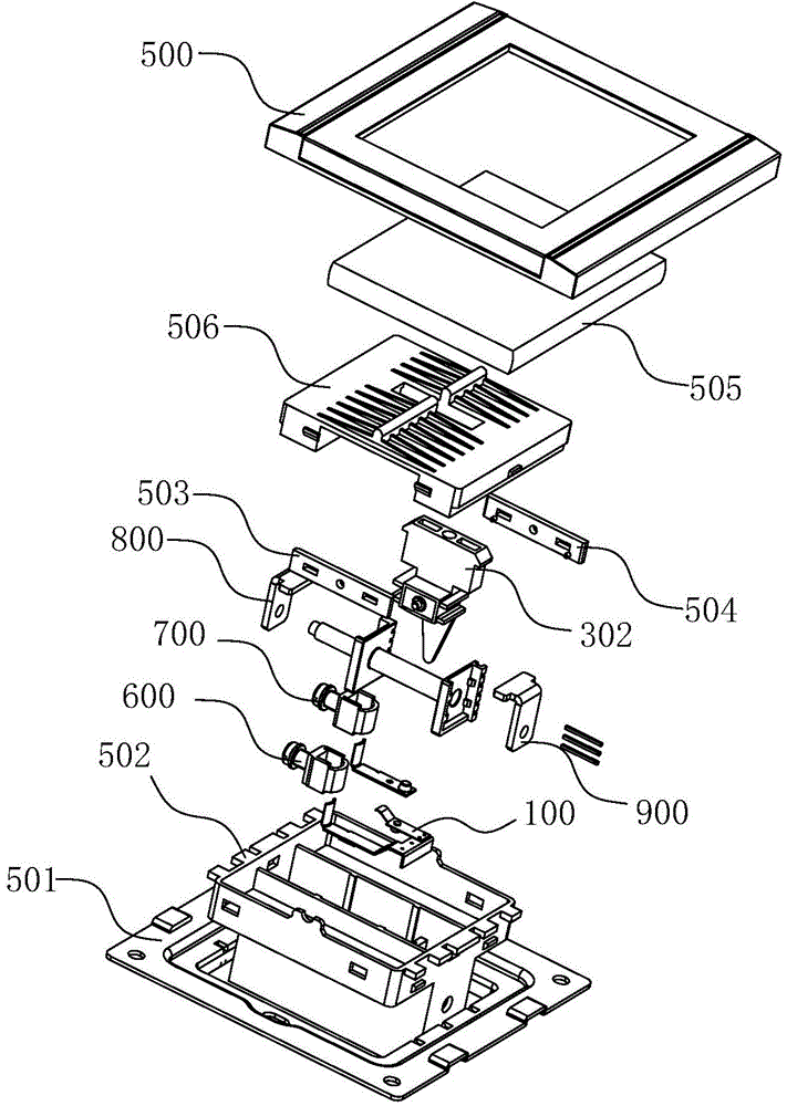
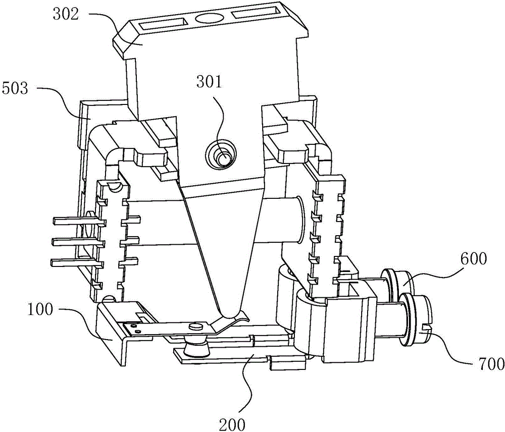
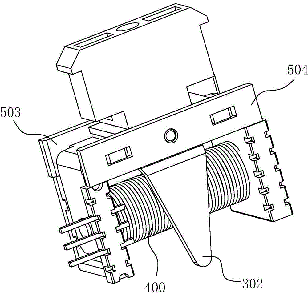
[0037] Such as Figure 1~6 As shown, in this embodiment, an intelligent switch according to the present invention includes a dynamic load assembly 100 and a static load assembly 200 that cooperate with each other, a local control device, a remote control device, and a device for limiting the dynamic load assembly 100. The position of the trigger device, the local control device and the remote control device control the movement of the trigger device, and the trigger device controls the selective contact or separation of the dynamic load assembly 100 and the static load assembly 200 to realize the closing or opening of the switch.

[0038] Further, the smart switch can realize local and remote control at the same time. When the remote control device controls the action of the trigger device, the swit...


PUM


Abstract

The invention discloses an intelligent switch which comprises a dynamical load assembly and static load assemblies, which are mutually coordinated, a local control device, a remote control device, and a triggering device used for limiting the position of the dynamical load assembly, wherein the local control device and the remote control device control the motion of the triggering device; the triggering device controls the dynamical load assembly and the static load assemblies to be selectively in contact or separated so as to realize on-off of the switch. According to the intelligent switch capable of realizing a local control function and a remote control function, the control manner of the switch is relatively flexible, the control position is diversified, and action on operating the switch is reduced. Besides the intelligent switch is modularized in structure, can be provided with a plurality of switch structures at the same time, and realizes seamless switch of single linkage, double linkage and multiple linkage.

Description

technical field [0001] The invention relates to the technical field of smart home products, in particular to a smart switch. Background technique [0002] "Wall switch" refers to an electrical switch installed on the wall, which is used to turn on and off the circuit to control the switch of the light. [0003] Chinese patent document CN 102044356 B discloses a wall switch, including a bracket, a mounting frame, a switch base, a decorative panel and a button, wherein the bracket is fixedly mounted on the mounting frame, the switch base is fixedly clamped on the bracket, and the button is fastened to the switch On the base, the decorative panel is fastened on the mounting frame. Mounting holes are provided on both sides of the mounting frame. The two sides of the button cover the top of the mounting hole. The mounting frame is located at the mounting hole and extends to both ends, that is, the mounting frame The overlapping position of the button is concavely set, so that wh...

Claims


Application Information

Patent Timeline
Patent Type & Authority Applications(China)
IPC IPC(8): H01H13/14H01H3/28
CPCH01H3/28
Inventor 李开波罗楠冯朝均刘金成
Owner EVE ENERGY CO LTD
Learn More