Airflow modification patch and method

A shroud, airflow technology, applied in the direction of affecting the air flow over the surface of the aircraft, transportation and packaging, vibration measurement in the fluid, etc., can solve problems such as adding aircraft parts, increasing the overall weight of the aircraft, affecting the connection of aircraft parts

Active Publication Date: 2015-05-27
MESSIER DOWTY
View PDF8 Cites 5 Cited by
  • Summary
  • Abstract
  • Description
  • Claims
  • Application Information

AI Technical Summary

Problems solved by technology

However, the inventors of the present application have discovered that existing noise reduction devices (e.g., fairings) can undesirably increase the overall weight of the aircraft
Moreover, existing noise reduction devices (e.g., fairings) can undesirably add skin to aircraft components (e.g., landing gear and / or high-lift devices) and affect connections between aircraft components
Fairings and the like also affect the cooling of components (eg brake components) and are usually directional meaning ineffective in tailwind conditions

Method used


Image

  • Airflow modification patch and method
  • Airflow modification patch and method
  • Airflow modification patch and method

Examples


Embodiment Construction

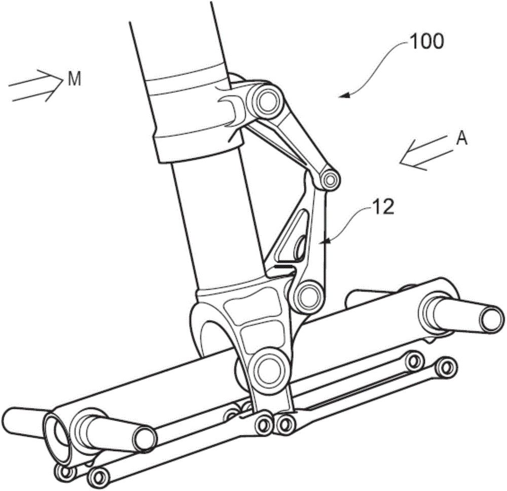
[0047] Fig. 1 shows a landing gear 100 in the prior art. The landing gear 100 includes a noise inducing area 12 in the form of a hinge of a twisted link. It is conceivable that the landing gear 100 includes many noise-generating components and areas suitable for take-off and landing, for example, the landing gear 100 is in an open state in the illustration.

[0048] Due to the movement of the aircraft to which the landing gear 100 is connected, the landing gear 100 generally moves in the direction of the arrow M, which is referred to as the landing gear movement direction M. Therefore, the airflow moves in the direction of arrow A relative to the landing gear 100, and this airflow is called airflow A. Airflow A can be considered as the main airflow or synthetic airflow from the forward and vertical velocity of the aircraft, which usually also includes a side wind component.

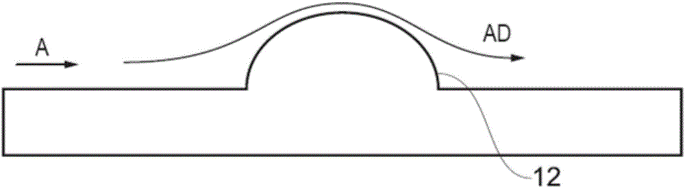
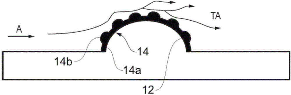
[0049] reference figure 2 , The figure schematically shows the noise inducing component 12 of the landing...


PUM


Abstract

An airflow modification patch 14 for reducing aero-acoustic noise generated by an aircraft assembly or component 12. The patch has a substrate 14a and a plurality of airflow disruption elements 14b. The patch is able to modify the aerodynamic airflow AD around the component to create a turbulated airflow TA. The turbulated airflow is intended to reduce the noise generated by air flowing around the assembly/component.

Description

Background technique [0001] An aircraft (for example, an airplane) generates a very loud noise during a landing approach (ie, close to landing). Much of this noise is caused by air flowing around open landing gear and / or high-lift devices (e.g., flaps and slats). [0002] Although the aircraft sails at a speed of about 80m / s during the landing sequence, the airflow around the noise-producing parts or the aircraft frame and the landing gear can reach a speed of about 300m / s, which generates about 200W of noise Sound energy dissipated in the form. The noise may be tonal noise, for example, whistle noise due to air flow on the cavity, low frequency rumble from wing box, or broadband noise, that is, noise in a wide frequency range. The turbulent airflow and wake noise around the aircraft are very loud, and the airflow around the aircraft (especially around the wings) will cause the components of the landing gear and the high-lift device to vibrate, which in turn may cause other comp...

Claims


Application Information

Patent Timeline
Patent Type & Authority Applications(China)
IPC IPC(8): B64C21/10B64C23/06B64C25/00
CPCB64C2230/14B64C21/10B64C23/06B64C2025/003Y02T50/10B64C23/00B64C25/00B64C1/40G01H3/00
Inventor 斯图尔特·莱西杰夫·卡姆勒皮特·迈克利兹
Owner MESSIER DOWTY
Why Eureka
Try Eureka