


Quick Research
Generate reliable direction feasibility study reports for your R&D in just a few steps.

Technical Q&A
Discover and master advanced knowledge NOW. Basics, ideas, possibilities, all at once.

Find Solutions
As an expert in R&D theories, this can generate solutions to your technical problems instantly.

Evaluate Feasibility
Analyze your overall solution with one click, know your potential R&D risks in advance.

Monitor Landscape
Get weekly tech updates, stay abreast of the latest tech innovations and key insights.
Improvements to radius inspection tools
A workpiece and ultrasonic technology, applied in the direction of material analysis, measuring devices, instruments, etc. using sound waves/ultrasonic waves/infrasonic waves, can solve problems such as difficulties, time-consuming, and affecting signal characteristics
- Summary
- Abstract
- Description
- Claims
- Application Information
AI Technical Summary
Problems solved by technology
Method used
Image

Examples
Embodiment Construction
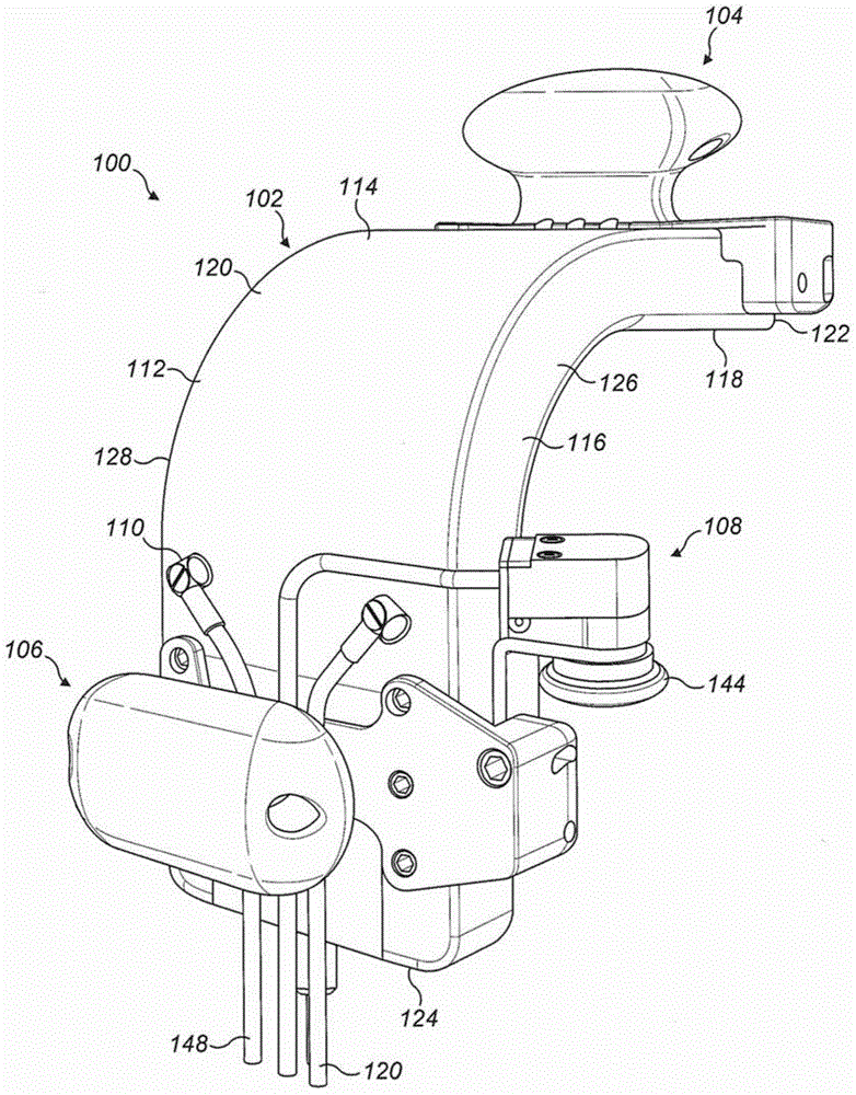
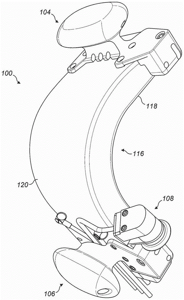
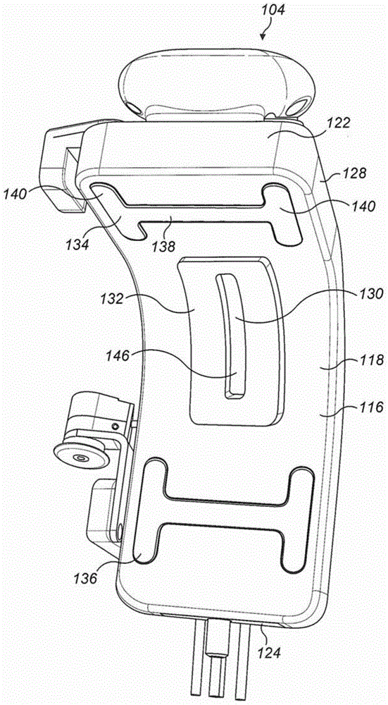
[0060] Figures 1 to 4d A first ultrasonic inspection probe 100 is shown in . The probe 100 includes a housing 102 , a first handle 104 , a second handle 106 and a rotary encoder 108 . The frame 102 includes a generally curved cross-section and a prismatic body 116 . The body 116 includes a first planar portion 110 , a 90-degree rounded portion 112 , and a second planar portion 114 . A planar portion 110 and a planar portion 114 extend from either end of the rounded portion 112 .
[0061] The probe 100 is configured to move along the elongated rounded workpiece in the axial direction of the rounded portion 112 . The terms “axial” and “radial” are used herein with respect to the radius 112 .
[0062] The main body 116 defines a workpiece facing surface 118 on one side and a frame loading surface 120 on an opposite side. In the illustrated embodiment, the body 116 has a female workpiece facing surface adapted to guide a male workpiece. It should be appreciated that the bod...
PUM
 Abstract
Description
Claims
Application Information
 - R&D Engineer
- R&D Manager
- IP Professional
- Industry Leading Data Capabilities
- Powerful AI technology
- Patent DNA Extraction
Browse by: Latest US Patents, China's latest patents, Technical Efficacy Thesaurus, Application Domain, Technology Topic, Popular Technical Reports.
© 2024 PatSnap. All rights reserved.Legal|Privacy policy|Modern Slavery Act Transparency Statement|Sitemap|About US| Contact US: help@patsnap.com