Ultrasonograph, ultrasonic transducer, examining instrument, and ultrasonographing device

a technology of ultrasonic transducers and ultrasonographs, which is applied in the direction of instruments, mechanical vibration separation, and specific gravity measurement, can solve the problems of general difficulty in achieving uniform formation, and lack of abnormality judging capability, so as to improve the acoustic transmission property between the different acoustic media

Active Publication Date: 2008-09-09
KK TOSHIBA
View PDF39 Cites 49 Cited by
  • Summary
  • Abstract
  • Description
  • Claims
  • Application Information

AI Technical Summary

Benefits of technology

[0037]Here, “to be acoustically connected” represents a state allowing acoustic transmission between different acoustic media. Incidentally,...

Problems solved by technology

What is becoming a problem at present in such an inspection method is that the underwater mechanical scan takes a lot of trouble and time so that, in the case of a semiconductor chip or the like, the chip becomes unusable after the inspection, and further, that lack of an abnormality judging capability may possibly be caused with the present inspection precision since the area and pitch of connection terminals of a semiconductor chip which is to be an inspection object are made narrower.
This leads to lack of the abnormality judging capability since the frequency is substantially correlated with resolution.
A film thickness may be small when a piezoelectric material with a high sensitivity is selected, and, though it is understood that a resultant increase in drive frequency enables a high resolution to be obtained, it is generally difficult to achieve uniform formation.
In this case, when the inspection object has a curved surface, such a problem arises that imaging of an internal part of the inspection object is not possible, and for example, the focus is not fixed to prevent high-precision imaging.
Further, an ultrasonic imaging de...

Method used


Image

  • Ultrasonograph, ultrasonic transducer, examining instrument, and ultrasonographing device
  • Ultrasonograph, ultrasonic transducer, examining instrument, and ultrasonographing device
  • Ultrasonograph, ultrasonic transducer, examining instrument, and ultrasonographing device

Examples


first embodiment

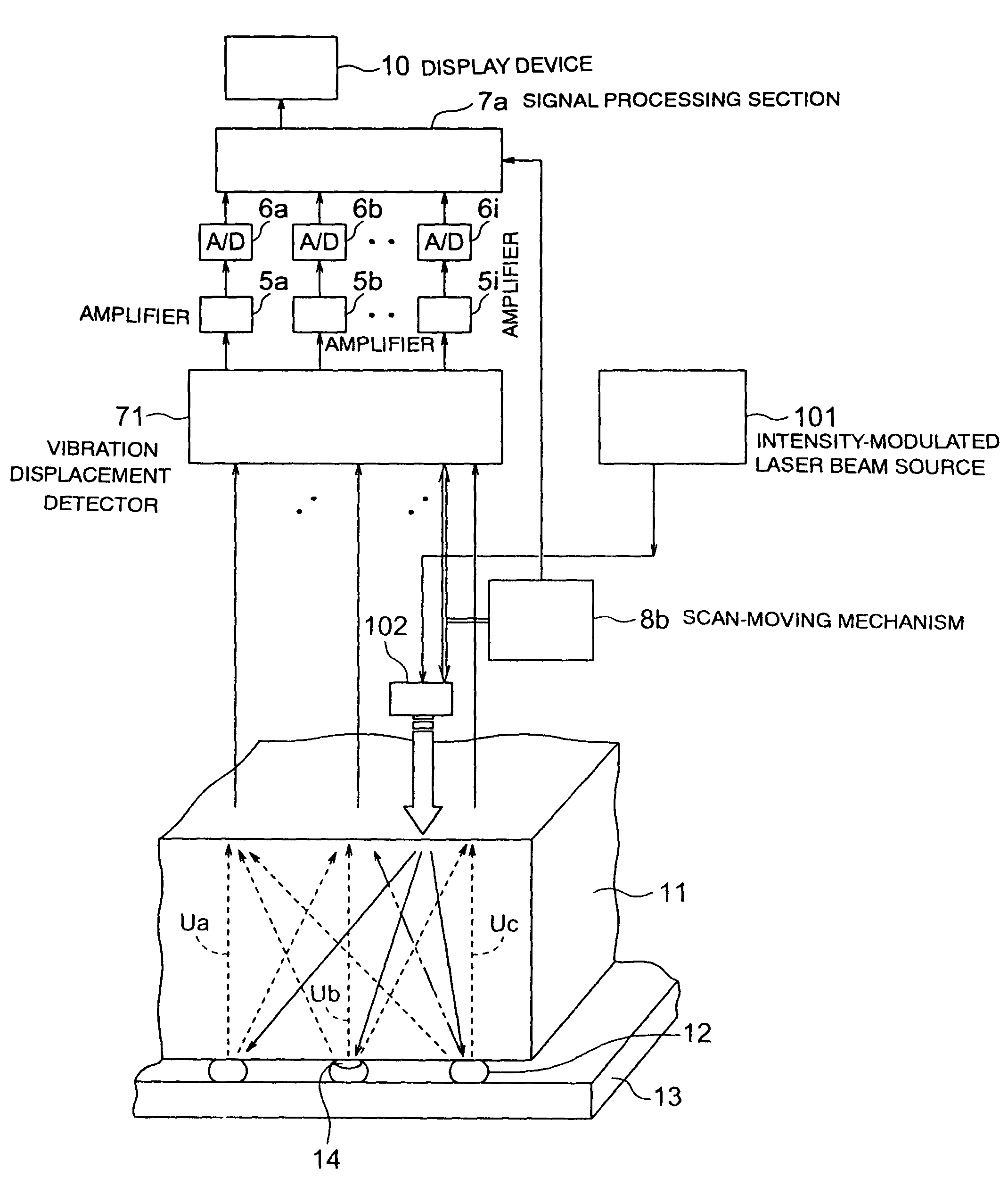
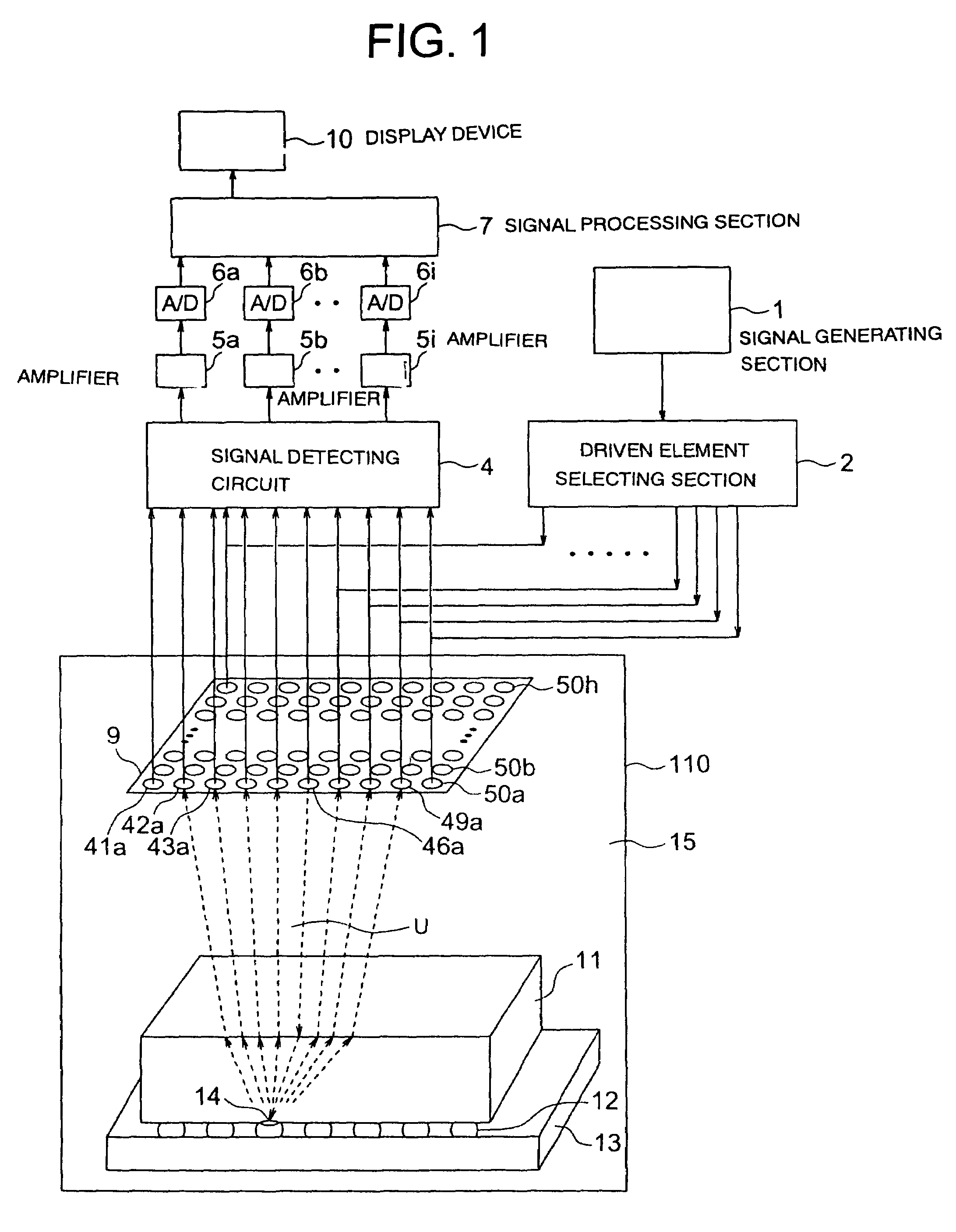
[0086]FIG. 1 is a block diagram explaining the configuration of an ultrasonograph according to a first embodiment of the present invention. As shown in this drawing, this ultrasonograph has an ultrasonic transducer 9, a signal generating section 1, a driven element selecting section 2, a signal detecting circuit 4, amplifiers 5a, 5b, . . . , 5i, A / D converters 6a, 6b, . . . , 6i, a signal processing section 7, a display device 10, and an inspection container 110. Water 15 is accommodated in the inspection container 110, in which the ultrasonic transducer 9, and a semiconductor chip 11, a wiring substrate 13, and connection solders 12, which are inspection objects (ultrasonic wave inspection objects) (hereinafter, the semiconductor chip 11, the wiring substrate 13, and the connection solders 12 are comprehensively referred to as “semiconductor chip 11 and so on”) are arranged, being immersed in the water 15.

[0087]The ultrasonic transducer 9 is so structured that a plurality of piezoe...

second embodiment

[0100]FIG. 3 is a block diagram explaining the configuration of an ultrasonograph according to a second embodiment of the present invention. In this drawing, the same numerals are assigned to the constituent elements which are previously explained, and explanation on the structure and operation thereof will be omitted. In this embodiment, unlike the above-described first embodiment, inspection objects are irradiated with an ultrasonic wave not via water but through the use of a shoe member.

[0101]As shown in this drawing, an ultrasonic transducer 9 is constituted with a shoe member 16 as a substrate. The shoe member 16 has a couplant 17 provided on a rear face thereof, and is pressed against a semiconductor chip 11 and so on as inspection objects via the couplant 17. The shoe member 16 is made of the same material (for example, silicon, epoxy, ceramic, or the like) as that of the semiconductor chip 11. The couplant 17 can be formed of the same material and to have the same thickness ...

third embodiment

[0105]FIG. 4 is a block diagram explaining the configuration of an ultrasonograph according to a third embodiment of the present invention. In this drawing, the same numerals are assigned to the constituent elements previously explained and explanation on the structure and operation thereof will be omitted. In this embodiment, piezoelectric elements are formed directly on a rear surface (opposite side of a functional surface) of a semiconductor chip 11a and so on as inspection objects, and contact terminals are brought into contact with upper electrodes thereof to supply drive voltages and take out generated voltages.

[0106]As shown in FIG. 4, a common electrode 58 is formed on the rear surface of the semiconductor chip 11a by, for example, sputtering, and piezoelectric layers 60a, 60b, 60c, 60d, . . . are further formed on the common electrode 58 in a matrix. Upper electrodes 59a, 59b, 59c, 59d, . . . are formed on the piezoelectric layers 60a and so on respectively. The piezoelectr...


PUM


Abstract

An ultrasonograph, an ultrasonic transducer, an inspection device, and an ultrasonic imaging device enabling easy and quick inspection and high-resolution or high-speed processing are provided. Barium titanate (BaTiO3) or lead zirconate titanate (PZT) is used for a piezoelectric material constituting the ultrasonic transducer, and the thickness thereof is 0.1 μm to 100 μm. Included therein are a drive section capable of driving an arbitrary one of piezoelectric layers, a detecting section detecting electrical signals generated by the plural piezoelectric layers based on echoes from an inspection object, the echoes being originated from an ultrasonic wave generated by the driven piezoelectric layer, and a processing section performing processing for visualizing a state of the inspection object based on the detected electrical signals.

Description

TECHNICAL FIELD[0001]The present invention relates to an ultrasonograph which inspects abnormality such as internal defects and peel-off in semiconductor chips, metal, ceramic components, resin, and so on through the use of ultrasonic waves, and to an ultrasonic transducer, an inspection device, and an ultrasonic imaging device therefor, and more particularly, to the ultrasonograph, the ultrasonic transducer, the inspection device, and the ultrasonic imaging device suitable for use in easily and quickly inspecting the abnormality with enhanced precision or higher speed.BACKGROUND ART[0002]Ultrasonic inspection of microscopic internal structures of semiconductor chips (integrating circuits: IC) and so on is carried out for the purpose of inspecting the bonding state of solders which join functional faces of the semiconductor chips and wiring substrates, and of fillers filled in gaps therebetween and for other purposes.[0003]Methods of such inspection include a method in which an insp...

Claims


Application Information

Patent Timeline
IPC IPC(8): G01N29/00G01N29/04B06B1/06G01N29/06G01N29/24G01N29/28G01S15/89H01L41/083
CPCB06B1/0622G01N29/06G01N29/2418G01N29/28G01N29/2437G01N2291/106G01N2291/0423G01N29/24
Inventor KARASAWA, HIROKAZUNAKAMOTO, MASAYUKIOCHIAI, MAKOTOFUKUDA, KATSUYOSHIHIRASAWA, TAIJIIKEDA, TAKAHIRO
Owner KK TOSHIBA
Why Eureka
Try Eureka