Potassium niobate deposited body and method for manufacturing the same, piezoelectric thin film resonator, frequency filter, oscillator, electronic circuit, and electronic apparatus

a technology of potassium niobate and deposited bodies, which is applied in the field of potassium niobate deposited bodies and methods for manufacturing the same, frequency filters, oscillators, etc., can solve the problem of difficult manufacturing of piezoelectric thin film resonators

Inactive Publication Date: 2006-10-05
SEIKO EPSON CORP
View PDF7 Cites 20 Cited by
  • Summary
  • Abstract
  • Description
  • Claims
  • Application Information

AI Technical Summary

Benefits of technology

[0038] In the second potassium niobate deposited body in accordance with an aspect of the invention, the lead zirconate titanate niobate layer may include niobium in 5 mol % or greater and 30 mol % or smaller with respect to niobium, titanium and zirconium.

Problems solved by technology

However, it may be difficult to manufacture a piezoelectric thin film resonator by forming a thin film of potassium niobate on a certain substrate having a large area.

Method used


Image

  • Potassium niobate deposited body and method for manufacturing the same, piezoelectric thin film resonator, frequency filter, oscillator, electronic circuit, and electronic apparatus
  • Potassium niobate deposited body and method for manufacturing the same, piezoelectric thin film resonator, frequency filter, oscillator, electronic circuit, and electronic apparatus
  • Potassium niobate deposited body and method for manufacturing the same, piezoelectric thin film resonator, frequency filter, oscillator, electronic circuit, and electronic apparatus

Examples


first embodiment

1. First Embodiment

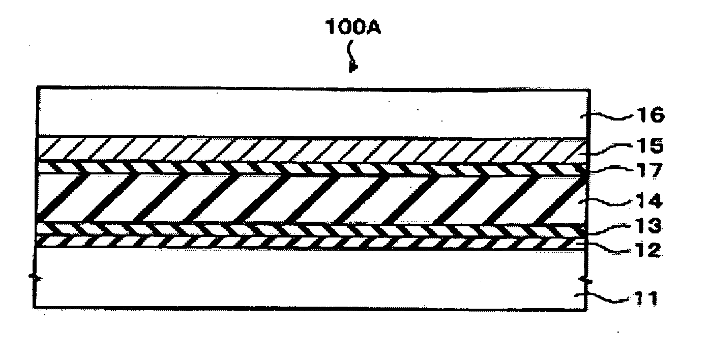
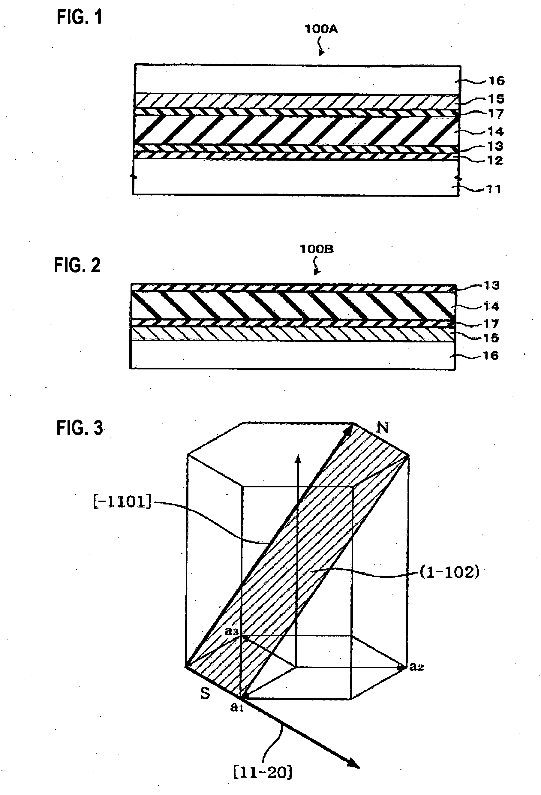
[0090] 1.1. FIG. 1 and FIG. 2 are cross-sectional views schematically showing a potassium niobate deposited body 100A and a potassium niobate deposited body 100B in accordance with an embodiment of the invention. As shown in FIG. 1, the first potassium niobate deposited body 100A of the present embodiment may include a substrate 11, a buffer layer 12 formed on the substrate 11, a lead zirconate titanate niobate layer 13 formed on the buffer layer 12, a potassium niobate layer 14 formed on the lead zirconate titanate niobate layer 13, an electrode layer 15 formed on the potassium niobate layer 14, and another substrate 16 formed on the electrode layer 15.

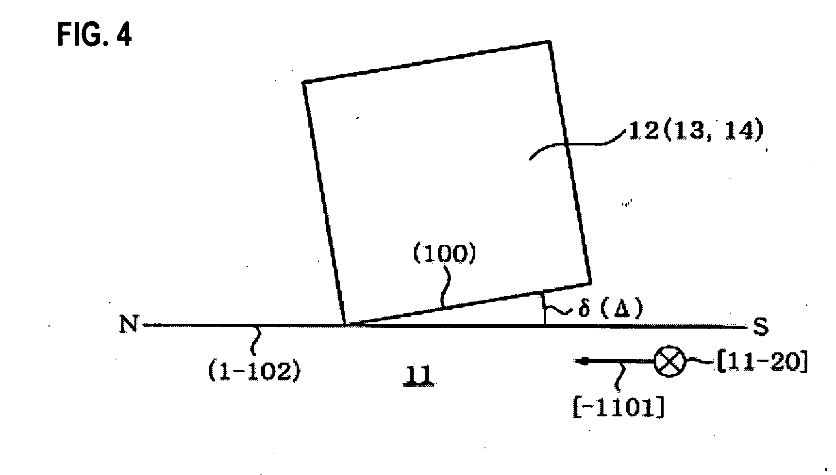
[0091] An R-plane sapphire substrate may be used as the substrate 11. The use of an R-plane sapphire substrate is desirable because the buffer layer 12, the lead zirconate titanate niobate layer 13 and the potassium niobate layer 14 can be epitaxially grown thereon, a substrate with a large surface area can be obt...

first experimental examples

1.4. FIRST EXPERIMENTAL EXAMPLES

[0183] In the present experimental example, potassium niobate deposited bodies 100A and 100B were formed according to a method described below.

[0184] First, a substrate 11 composed of an R-plane sapphire single crystal plate was degreased and washed through soaking the substrate 11 in an organic solvent with an ultrasonic washing machine. As the organic solvent, a 1:1 mixed solution of ethyl alcohol and acetone was used. After loading the substrate 11 onto a substrate holder, the substrate 11 was introduced together with the substrate holder in a vacuum apparatus whose back pressure at room temperature was 1×10⁻⁷ Torr, oxygen gas was introduced such the oxygen partial pressure became 5×10⁻⁵ Torr, and then the substrate was heated to elevate its temperature to 400° C. at a rate of 20° C. / minute with an infrared ray lamp. At this time, as shown in FIG. 5A, a pattern obtained by the reflection high speed electron beam diffraction (i.e., reflection high ...

second embodiment

2. Second Embodiment

[0206] 2.1. FIG. 16 and FIG. 17 are cross-sectional views schematically showing potassium niobate deposited bodies 200A and 200B in accordance with an embodiment of the invention.

[0207] The first potassium niobate deposited body 200A of the present embodiment shown in FIG. 16 may include a first substrate 11, a buffer layer 12 formed on the first substrate 11, a first lead zirconate titanate niobate layer 13 formed on the buffer layer 12, a potassium niobate layer 14 formed on the first lead zirconate titanate niobate layer 13, a second lead zirconate titanate niobate layer 17 formed on the potassium niobate layer 14, an electrode layer 15 formed on the second lead zirconate titanate niobate layer 17, and another substrate (hereafter referred to as a “second substrate”) 16 formed on the electrode layer 15. The present embodiment is different from the first embodiment in that the second lead zirconate titanate niobate layer 17 is further provided over the potassi...


PUM

PropertyMeasurementUnit
angleaaaaaaaaaa
angleaaaaaaaaaa
crystallization temperatureaaaaaaaaaa

Abstract

A potassium niobate deposited body includes an R-plane sapphire substrate, a buffer layer composed of a metal oxide and formed above the R-plane sapphire substrate, a lead zirconate titanate niobate layer formed above the buffer layer, a potassium niobate layer or a potassium niobate solid solution layer formed above the lead zirconate titanate niobate layer, an electrode layer formed above the potassium niobate layer or the potassium niobate solid solution layer, and another substrate formed above the electrode layer.

Description

[0001] The entire disclosure of Japanese Patent Application No. 2005-097977, filed Mar. 30, 2005 is expressly incorporated by reference herein. BACKGROUND [0002] 1. Technical Field [0003] The present invention relates to potassium niobate deposited bodies and methods for manufacturing the same, piezoelectric thin film resonators, frequency filters, oscillators, electronic circuits, and electronic apparatuses. [0004] 2. Related Art [0005] In the telecommunications field, accompanying the increase in the transmission rate, the transmission frequency is advancing toward higher frequencies. Piezoelectric thin film resonators (i.e., film bulk acoustic resonators: FBARs) are attracting attention as devices for achieving such higher frequencies. Because the development of piezoelectric thin film resonators is also directed toward achieving further miniaturization and higher efficiency, a larger electromechanical coupling coefficient is needed. [0006] It has been found that a single crystal...

Claims


Application Information

Patent Timeline
Patent Type & Authority Applications(United States)
IPC IPC(8): B32B15/04B32B9/00B32B19/00C01G33/00C30B29/30H01L41/09H01L41/187H01L41/313H01L41/316H01L41/319H01L41/39H03H3/02H03H9/17
CPCH03H3/02H03H9/02031H01L41/318H03H2003/023H01L41/1876H03H9/174H10N30/8554H10N30/078
Inventor HIGUCHI, TAKAMITSUKIJIMA, TAKESHIUENO, MAYUMI
Owner SEIKO EPSON CORP
Why Eureka
Try Eureka