

Configurations and methods for ultrasound time of flight diffraction analysis
a technology of ultrasound time and flight diffraction analysis, which is applied in the field of non-destructive analysis of materials, can solve the problems of inconvenient measurement of the inability to accurately determine the inability to accurately measure the quality of the weld,
- Summary
- Abstract
- Description
- Claims
- Application Information
AI Technical Summary
Benefits of technology
Problems solved by technology
Method used
Image

Examples
Embodiment Construction
” below apply.
[0014]In further preferred aspects, the information in contemplated methods may further include advice that the lack of fusion is detected by a loss of at least one of a back wall echo and / or a lateral wave, and / or advice that the apparatus will detect a flaw in the polymeric material (e.g., flaw size less than 4% of the thickness of the polymeric material), when the polymeric material has a thickness of up to 4 inches.
BRIEF DESCRIPTION OF THE DRAWING
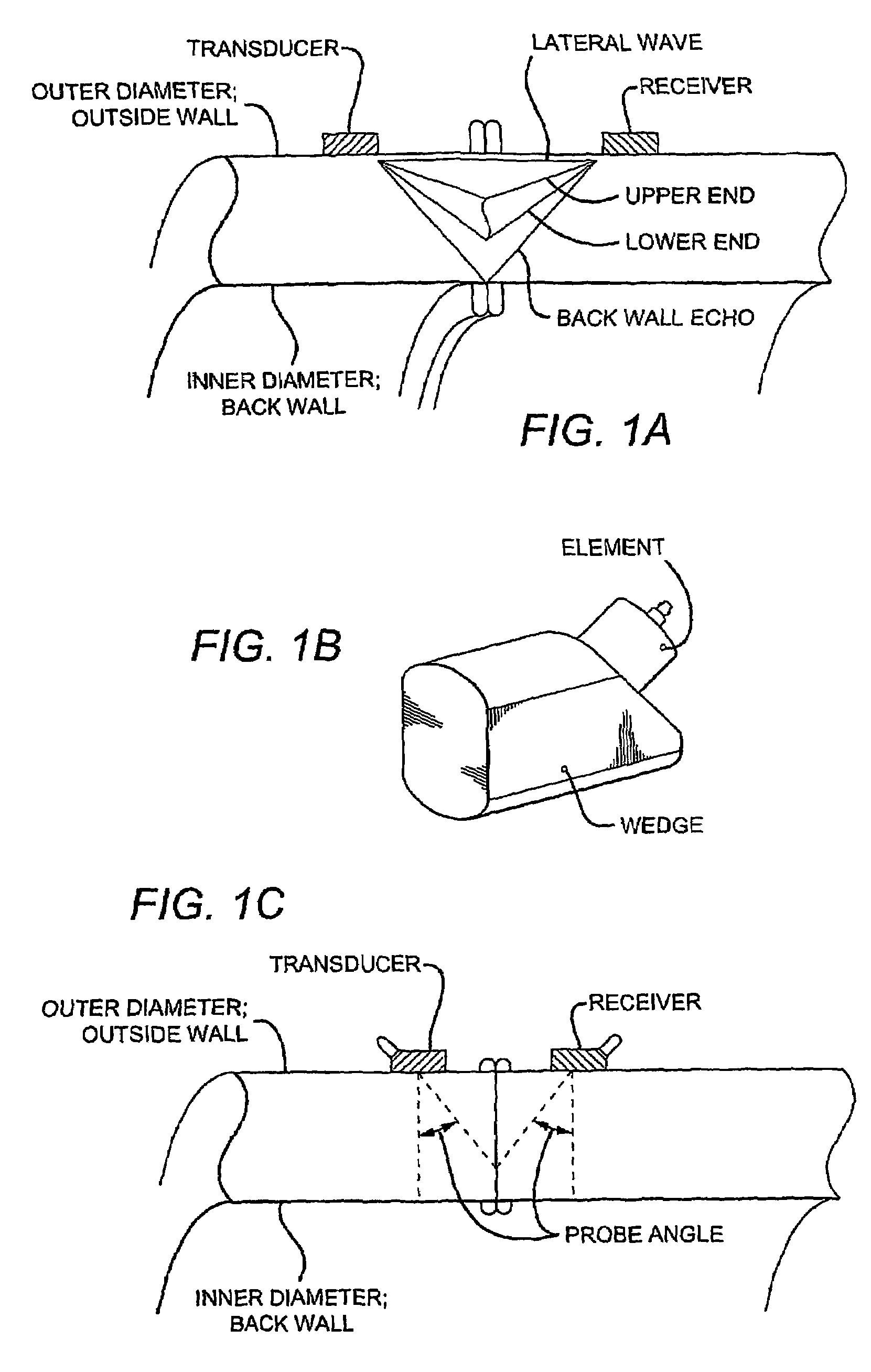
[0015]FIG. 1A is a schematic of an exemplary apparatus according to the inventive subject matter in contact with a plastic pipe having a butt weld.
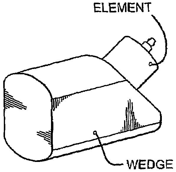
[0016]FIG. 1B is a schematic of an exemplary transducer of the apparatus of FIG. 1A.
[0017]FIG. 1C is a schematic of an exemplary probe angle according to the inventive subject matter.
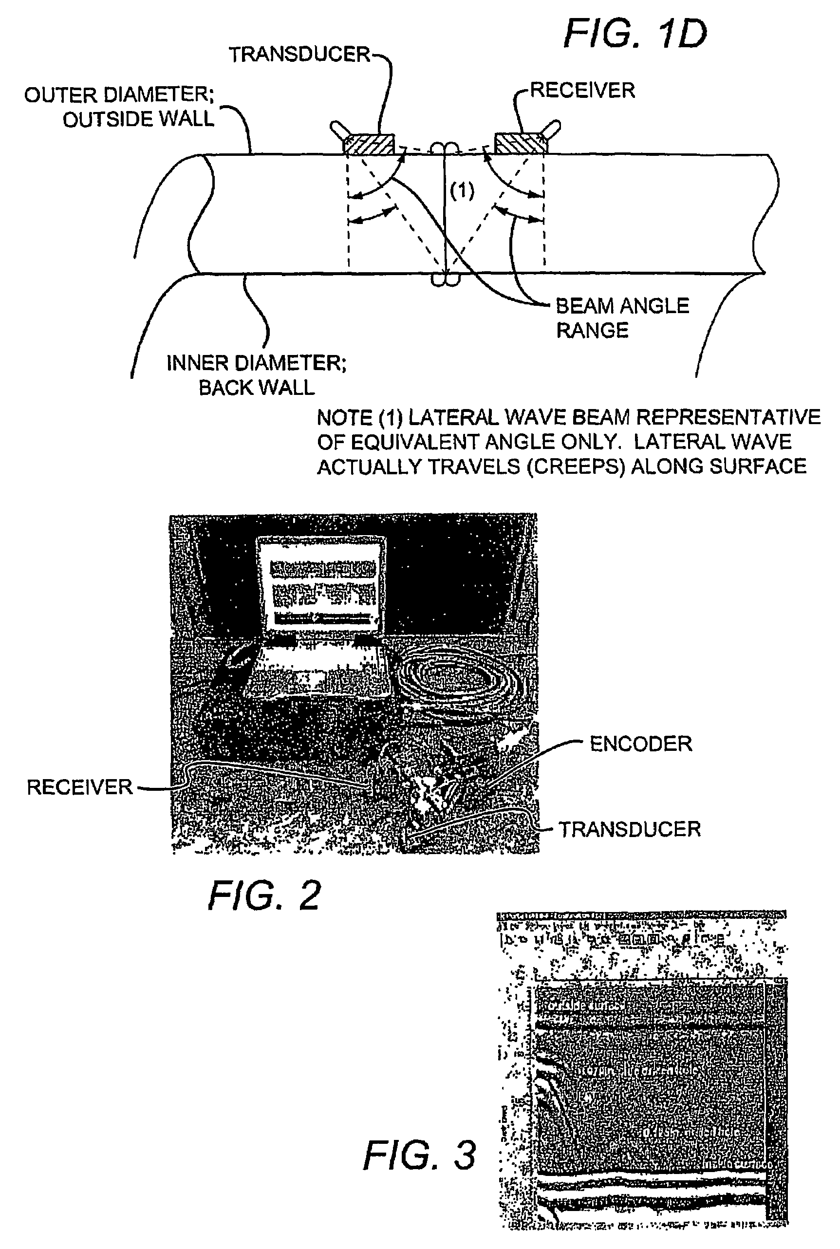
[0018]FIG. 1D is a schematic of an exemplary beam angle range according to the inventive subject matter.
[0019]FIG. 2 is a photograph of an exemplary UT-TOFD test system according to the inventive su...
PUM
| Property | Measurement | Unit |
|---|---|---|
| frequency | aaaaa | aaaaa |
| frequency | aaaaa | aaaaa |
| beam angle | aaaaa | aaaaa |
Abstract
Description
Claims
Application Information