Leakage flux probe for non-destructive leakage flux-testing of bodies consisting of magnetizable material

Inactive Publication Date: 2013-05-16
VALLOUREC DEUT
View PDF4 Cites 3 Cited by
  • Summary
  • Abstract
  • Description
  • Claims
  • Application Information

AI Technical Summary

Benefits of technology

The patent explains a technique to improve the detection of flaws in a product by using a special sensor package. The sensors are placed at different angles, which allows the device to detect flaws in both longitudinally and obliquely oriented directions. This increases the likelihood of detecting flaws and improves the signal-noise ratio. Overall, the technique helps to improve the quality and accuracy of flaw detection.

Problems solved by technology

During testing, unidirectional field magnetization of the pipe is typically used, since flaws on the outer surface and on the inner surface of the pipe can be detected thereby.
They can be caused, e.g., by faulty inner tools or rollers or even by flaws in the basic material.
However, in the case of longitudinal and transverse flaw testing, oblique flaws extending obliquely with respect to the magnetic field direction are only identified to a limited extent, since the sensitivity (directional characteristic) of the individual sensors rapidly decreases as the oblique position of the flaw increases.
Similarly, oblique flaw testing in which the main testing direction is, e.g., at an angle of 45° in relation to the longitudinal axis of the pipe, is typically not suitable for also detecting longitudinal and transverse flaws to the same degree.

Method used


Image

  • Leakage flux probe for non-destructive leakage flux-testing of bodies consisting of magnetizable material
  • Leakage flux probe for non-destructive leakage flux-testing of bodies consisting of magnetizable material
  • Leakage flux probe for non-destructive leakage flux-testing of bodies consisting of magnetizable material

Examples


Embodiment Construction

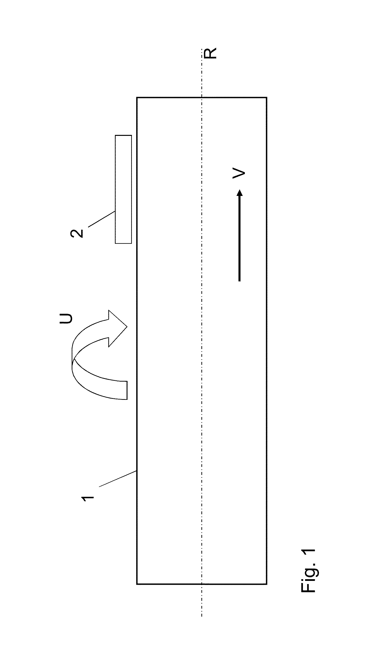
[0046]Referring now to the drawings and the illustrative embodiments depicted therein, FIG. 1 illustrates a schematic view of a device for non-destructive leakage flux-testing of a hot-rolled seamless pipe 1, made of ferromagnetic steel, for longitudinal flaws and oblique flaws. Pipe 1 typically is illustrated as having a central pipe axis R which extends in the longitudinal direction of the pipe 1. The core component of the testing device is a leakage flux probe which is part of a testing shoe 2. For testing purposes, the pipe 1 is moved in the feed direction V and the testing shoe 2 is moved in a circumferential direction U around the pipe 1, so that the pipe 1 is examined on a helical track.

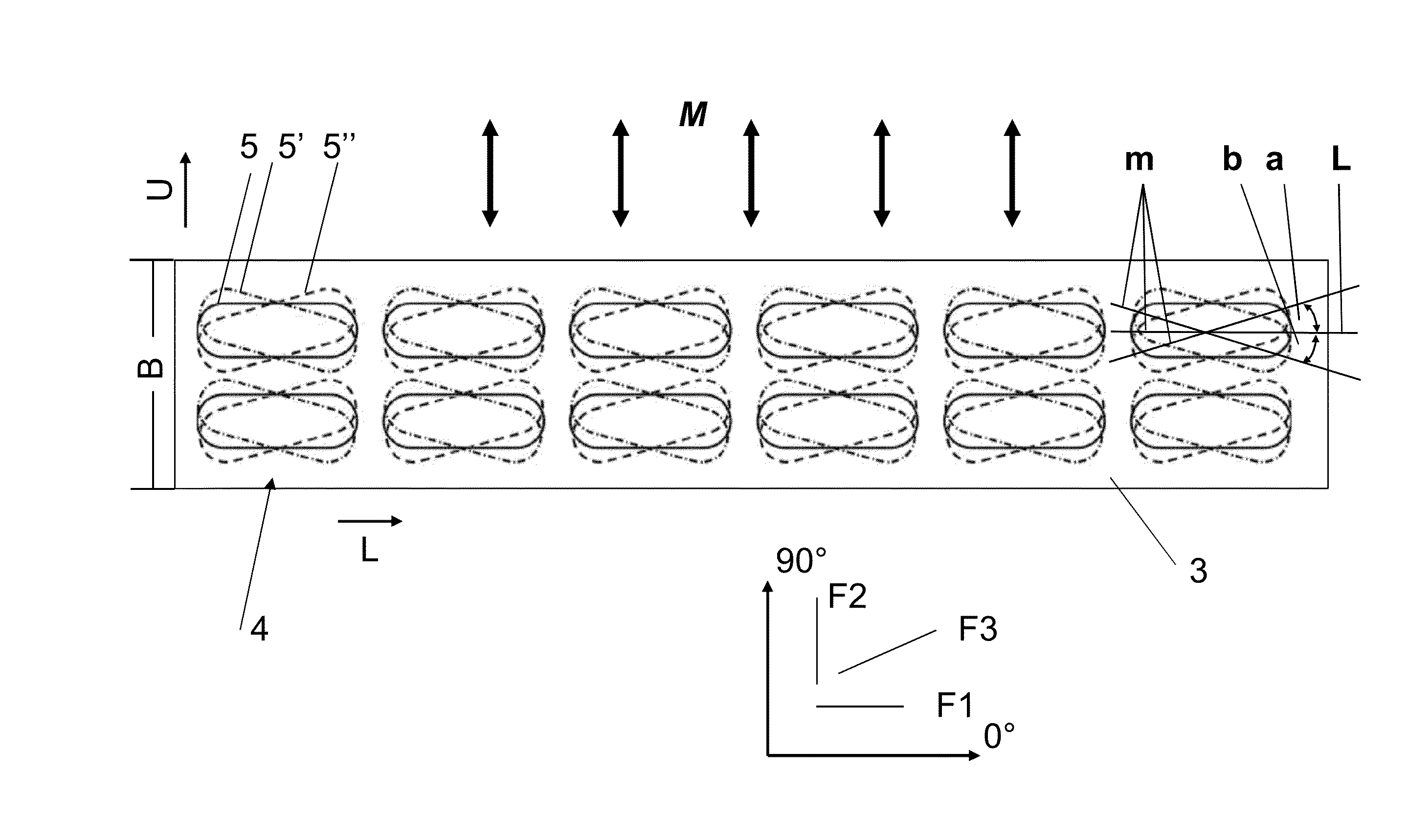
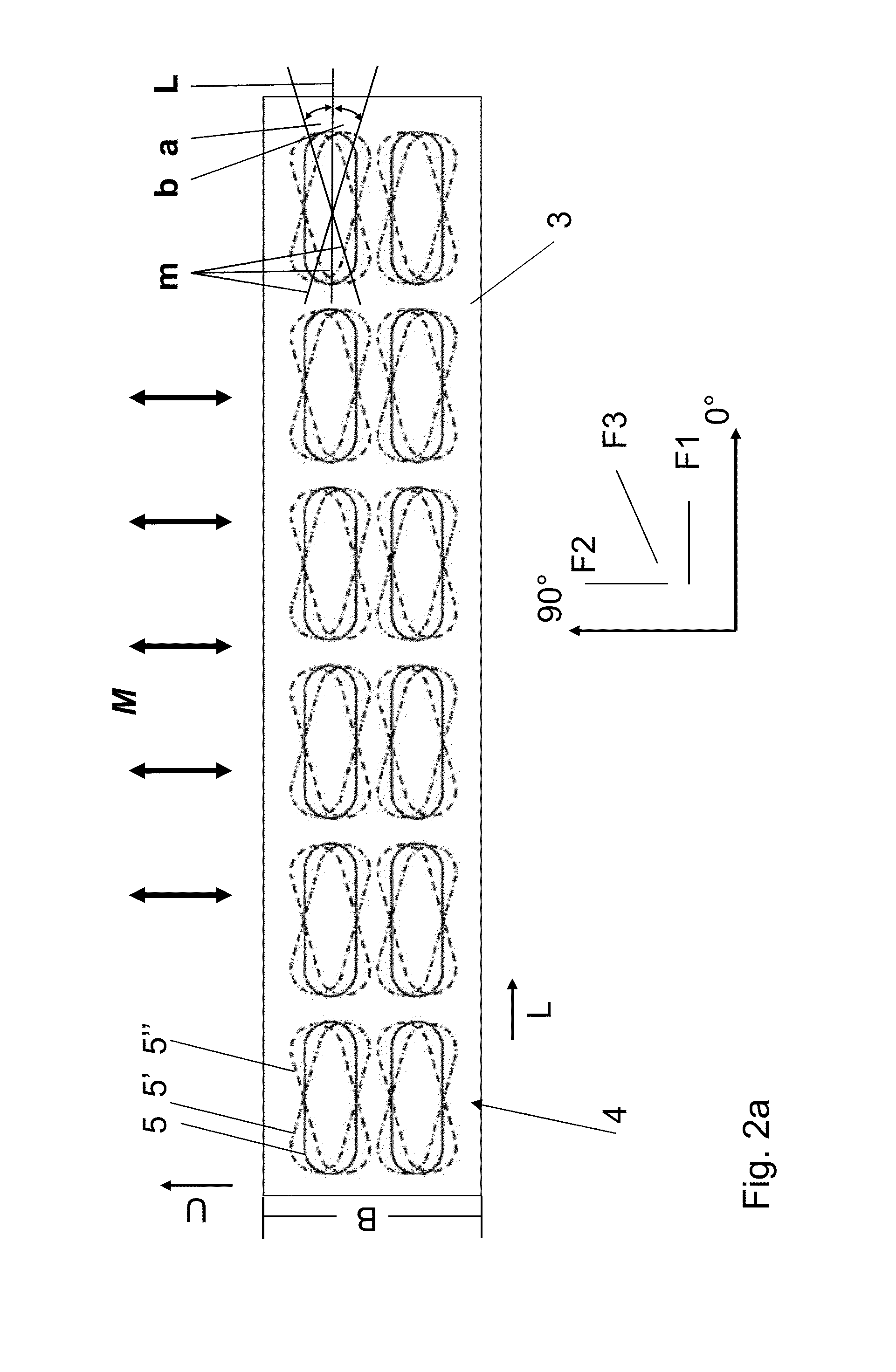
[0047]The device for non-destructive leakage flux-testing includes not only a testing shoe 2 but also a magnetization unit, not illustrated, by which pipe 1 is magnetized by a magnetic field for leakage flux testing. In this case, pipe 1 is magnetized by a unidirectional field. The magnetic fi...


PUM


Abstract

A leakage flux probe for non-destructive leakage flux-testing of bodies consisting of magnetizable material, in particular of pipes consisting of ferromagnetic steel, having a plurality of sensors disposed one behind the other in a straight line for detection of near-surface flaws in the body. In order to create a leakage flux probe for non-destructive leakage flux-testing of bodies consisting of magnetizable material, in particular of pipes consisting of ferromagnetic steel, which in a main testing direction has a broadened directional characteristic. At least two similar sensors are disposed and interconnected in a sensor package in a different angular orientation with respect to the main testing direction one above the other, one next to the other or one lying inside the other. The sensor packages disposed generally in a line one behind the other can be influenced individually by the generated leakage flux of an existing flaw. The individual sensors of the sensor package are spaced apart from each other by such a small spaced interval that the interconnected sensors of a sensor package are collectively influenced by the generated leakage flux of an existing flaw.

Description

BACKGROUND OF THE INVENTION[0001]The invention relates to a leakage flux probe for non-destructive leakage flux-testing of bodies consisting of magnetizable material, such as pipes consisting of ferromagnetic steel.[0002]For the purpose of non-destructive and near-surface testing of bodies consisting of magnetizable materials, it is generally known to use the so-called leakage flux method. For this purpose, the bodies which are to be tested are magnetized temporarily by electromagnets, cylinder coils or current linkage. In a homogeneous and flawless ferromagnetic material, the magnetic field lines are distributed uniformly over the surface. If the homogeneity of the material is disrupted by near-surface discontinuities, such as, e.g., cracks, cavities, inclusions, pores or laminations, then magnetic field lines can emerge as so-called leakage flux outside the workpiece in the region of the discontinuities. This leakage flux can be detected in a contacting or contactless manner by pr...

Claims


Application Information

Patent Timeline
IPC IPC(8): G01N27/82
CPCG01N27/87G01N27/82
Inventor KAACK, MICHAELFISCHER, GERTNEMITZ, OLIVERSCHMITTE, TILLNITSCHE, STEFAN
Owner VALLOUREC DEUT
Why Eureka
Try Eureka