Ultrasonic inspection apparatus, system, and method

a technology of ultrasonic inspection and apparatus, applied in the direction of structural/machine measurement, instruments, specific gravity measurement, etc., can solve the problems of introducing additional time and labor, limiting the inspection speed and efficiency of the structure, and not always being able to perform continuous scanning of the structure with holes, etc., to achieve the effect of increasing inspection speed and efficiency and reducing cos

Active Publication Date: 2010-01-05
THE BOEING CO
View PDF104 Cites 48 Cited by
  • Summary
  • Abstract
  • Description
  • Claims
  • Application Information

AI Technical Summary

Benefits of technology

[0011]The present invention provides apparatus, systems, and methods for inspecting a structure using a motion control system, a probe extension coupler, and an inspection probe capable of performing pulse echo ultrasonic inspection. Apparatus, systems, and methods of the present invention provide the capability to non-destructively inspect large, contoured, composite structures with increased speed of inspection provided by a pedestal robot mounted on a rail system, an array of transducers, and a probe capable of scanning over holes and off edges of the structure.
[0012]For continuous scanning applications, embodiments of apparatus, systems, and methods of the present invention use a motion control system and an extension coupler to press a part-riding probe against the surface of the structure, typically using one or more sled appendages and axial and extension braking systems, thereby reducing the necessary sophistication of the motion control system to maintain the probe in a predefined orientation and predefined position with respect to the surface of the structure.
[0015]Embodiments of apparatus, systems, and methods of the present invention typically operate in array modes using an array of pulse echo ultrasonic transducers, thereby increasing inspection speed and efficiency while reducing cost. Apparatus, systems, and methods of the present invention are also capable of operating with a single or a plurality of pulse echo ultrasonic transducers.

Problems solved by technology

In the field, access to interior surfaces of the structure is often restricted, requiring disassembly of the structure, introducing additional time and labor.
For example, typical defects in composite sandwich structures, generally made of one or more layers of lightweight honeycomb or foam core material with composite or metal skins bonded to each side of the core, include disbonds which occur at the interfaces between the core and the skin or between the core and a buried septum.
However, it has traditionally not always been possible to perform continuous scanning of a structure with holes and off the edges of the structure.
However, for through-transmission ultrasonic inspection, a semi-automated inspection system requires access to both sides or surfaces of a structure which, at least in some circumstances, will be problematic, if not impossible, particularly for semi-automated systems that use a fixed frame for control of automated scan heads.
Conventional automated scanning systems, such as the AUSS-X system, therefore require access to both sides or surfaces of a structure for through transmission inspection which, at least in some circumstances, will be problematic, if not impossible, particularly for very large or small structures.
It is often complicated, time consuming, and expensive to program and control an automated motion control system with respect to surface contours of a structure to within sufficient precision for performing inspection and maintaining consistent quality of inspection.
Furthermore, variances in surface contours of the actual structure may not precisely match the data for the surface contours of the structure provided to the automated motion control system, thereby disturbing the automated motion control system's ability to maintain the inspection probe in consistent orientation with respect to the structure.

Method used


Image

  • Ultrasonic inspection apparatus, system, and method
  • Ultrasonic inspection apparatus, system, and method
  • Ultrasonic inspection apparatus, system, and method

Examples


Embodiment Construction

[0026]The present invention will be described more fully with reference to the accompanying drawings. Some, but not all, embodiments of the invention are shown. The invention may be embodied in many different forms and should not be construed as limited to the described embodiments. Like numbers and variables refer to like elements and parameters throughout the drawings.

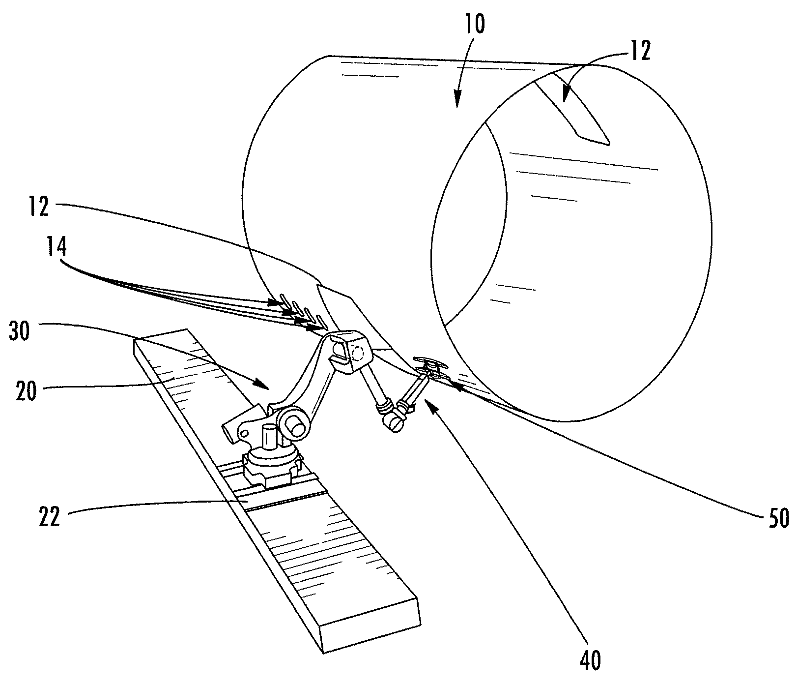
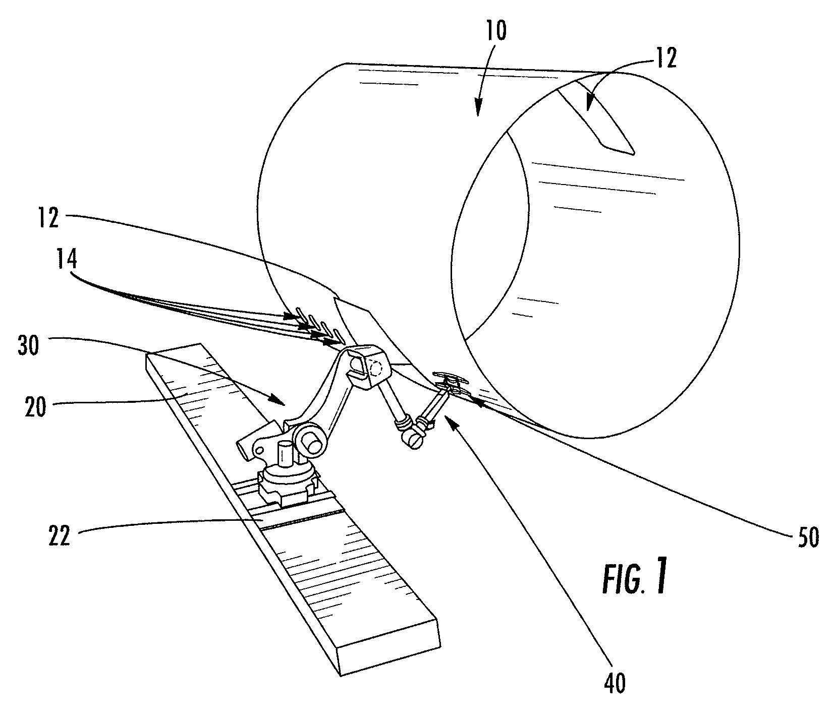
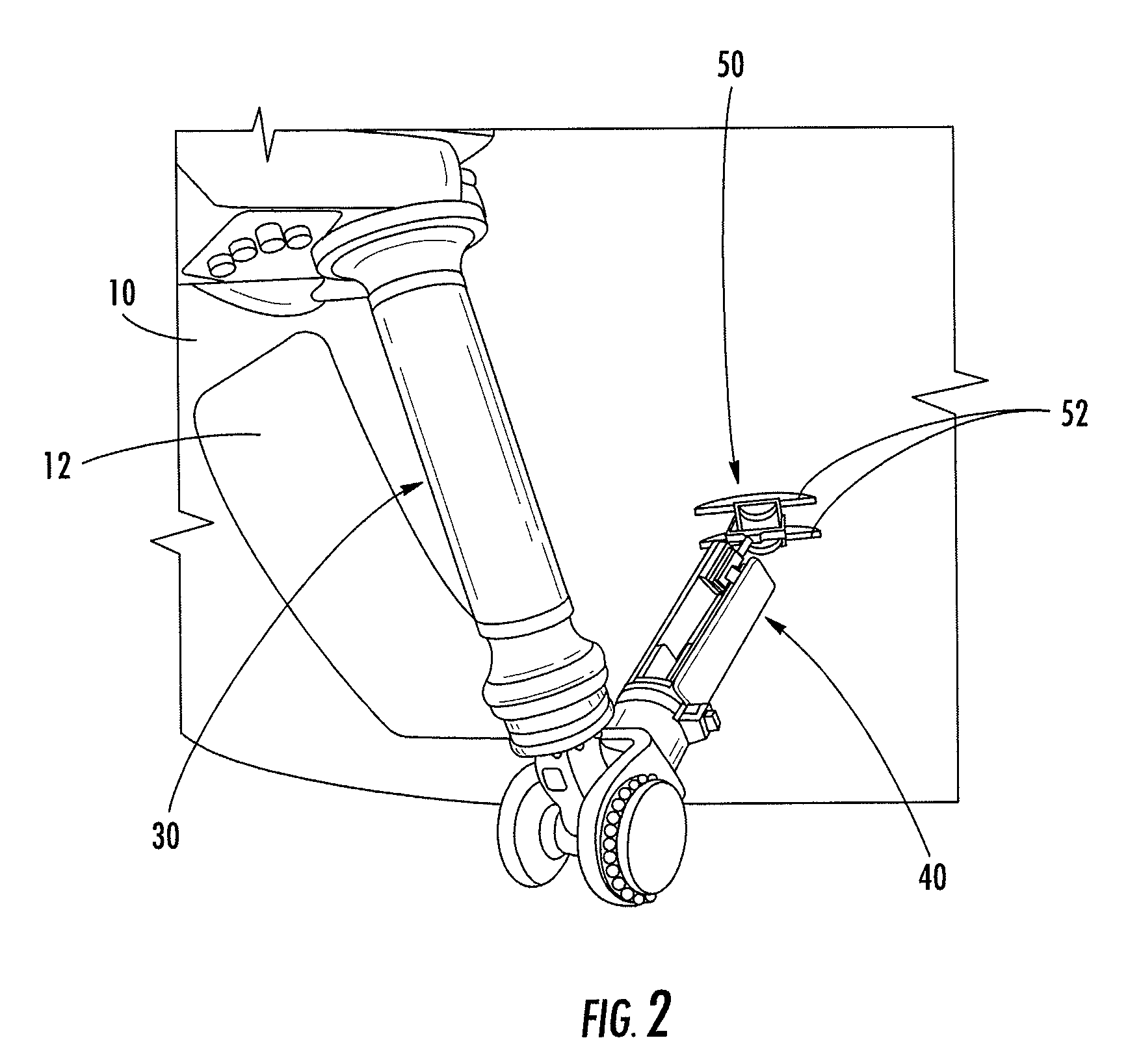
[0027]The term “motion control system” refers generally to a system which provides motion and control (controlled motion) to another device, such as an attached inspection probe, extension coupler, drilling apparatus, or other device attached to a distal end of the motion control system. A motion control system may include one or more subsystems, such as a rail system or a robot motion control system. A motion control system may include a controller, such as a computer or similar hardware and / or software device, for issuing electronic signals to command the controlled motion of the motion control system. A subsystem ...


PUM

PropertyMeasurementUnit
diameteraaaaaaaaaa
pressureaaaaaaaaaa
pressureaaaaaaaaaa

Abstract

Improved apparatus, systems, and methods for inspecting a structure are provided that use a pedestal robot mounted on a rail system, a probe extension coupler, and an inspection probe capable of performing pulse echo ultrasonic inspection. A probe may also include sled appendages and an axial braking system to inspect over holes and off edges. A probe may also include an ultrasonic pulse echo transducer array for high rate inspection; the transducer array may be mounted in a bubbler shoe for individually coupling each of the transducers in the array. A rail system may also include an optical encoder for providing location information for the robot and axial braking system. A probe extension coupler presses the inspection probe against the structure for adjusting to changes in surface contours.

Description

CROSS-REFERENCE TO RELATED APPLICATIONS[0001]This application is a continuation of and claims priority to U.S. patent application Ser. No. 11 / 178,584, filed Jul. 11, 2005, the content of which are incorporated herein by reference in its entirety.[0002]The contents of U.S. Pat. No. 6,722,202; application Ser. No. 10 / 752,890, entitled “Non-Destructive Inspection Device for Inspection Limited-Access Features of a Structure,” filed Jan. 7, 2004, now U.S. Pat. No. 7,231,826; application Ser. No. 10 / 943,088, entitled “Magnetically Attracted Inspecting Apparatus and Method Using a Ball Bearing,” filed Sep. 16, 2004; application Ser. No. 10 / 943,135, entitled “Magnetically Attracted Inspecting Apparatus and Method Using a Fluid Bearing,” filed Sep. 16, 2004, now U.S. Pat. No. 7,320,249; and application Ser. No. 11 / 178,637, entitled “Ultrasonic Array Probe Apparatus, System, and Method for Traveling over Holes and off Edges of a Structure,” filed Jul. 11, 2005, now U.S. Pat. No. 7,337,673, ar...

Claims


Application Information

Patent Timeline
Patent Type & Authority Patents(United States)
IPC IPC(8): G01N29/265G01N29/06G01M99/00
CPCG01N29/265G01N29/343G01N2291/044G01N2291/106
Inventor KENNEDY, JAMES C.LITTLE, MARK L.UYEHARA, CLYDE T.
Owner THE BOEING CO
Why Eureka
Try Eureka