
On-demand multiple power source management system, on-demand multiple power source management system program and computer-readable recording medium on which said program is recorded

A technology of a power management system and a power management device, which is applied in the directions of computer control, power network operating system integration, computing, etc., can solve the problems of increasing battery introduction costs, increasing costs, and reducing households, etc.

Inactive Publication Date: 2015-05-27
NITTO DENKO CORP
View PDF11 Cites 4 Cited by
  • Summary
  • Abstract
  • Description
  • Claims
  • Application Information

AI Technical Summary

Problems solved by technology

However, the current storage battery management is simple management such as schedule management such as charging at night and discharging during the day, and charging when solar power generation is leftover, and there is no effective and adaptive management according to the power usage pattern of each person. Charge and discharge management
In addition, in order to be able to cope with any power usage pattern, there is a tendency to increase the cost of introducing a storage battery with excessive capacity and charging and discharging power.
[0024] In addition, in the case of reducing the peak power consumption of households, etc., only by introducing storage batteries without introducing an on-demand power control system, the capacity of the storage batteries cannot be reduced enough to meet the demand. The degree of peak power
Therefore, in accordance with the increase in the capacity of the storage battery required in this case, the storage battery introduction cost also increases.

Method used


Image

  • On-demand multiple power source management system, on-demand multiple power source management system program and computer-readable recording medium on which said program is recorded
  • On-demand multiple power source management system, on-demand multiple power source management system program and computer-readable recording medium on which said program is recorded
  • On-demand multiple power source management system, on-demand multiple power source management system program and computer-readable recording medium on which said program is recorded

Examples


no. 1 approach

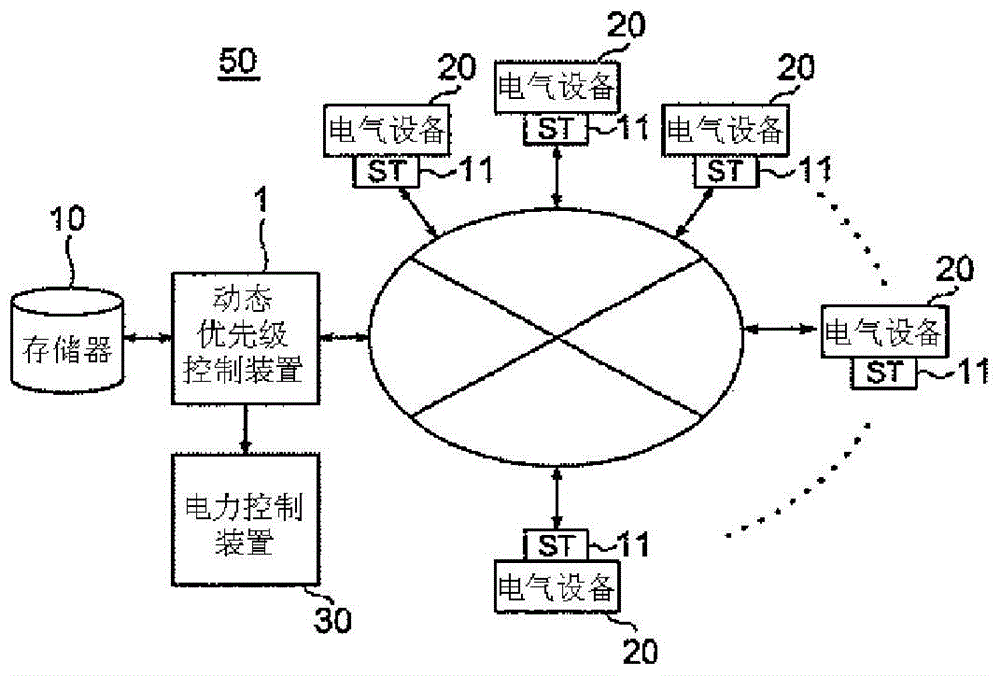
[0134] Figure 8 yes means figure 1 A functional block diagram of a first embodiment of the functions provided by the priority device shown.

[0135] Figure 8 Reference numeral 1 denotes a priority device, reference numeral 10 denotes its memory, and reference numeral 11 denotes ST, which is composed of an initial target value updating unit 120 and a power mediation unit 122 . Reference numeral (1) denotes power consumption transmitted from the ST. Furthermore, prior to its operation, the priority device converts the above-mentioned power consumption into a power usage plan for determining the power usage for each minimum control interval τ as preprocessing, and converts the power usage plan, the instantaneous power of the initial target value, and the maximum The instantaneous power is stored to the memory 10 . Reference numeral (2) denotes a power request message sent from the ST, which is sent to the power mediation unit 122 described above.

[0136] Furthermore, the...

no. 2 approach

[0217] The above-mentioned priority device 1 can finally control the instantaneous power to be below the maximum instantaneous power, and can perform control to satisfy the target value C of the accumulated electric power. The maximum instantaneous power is exceeded. A second embodiment to cope with this situation will be described.

[0218] Figure 16 It is a functional block diagram illustrating the functions of a plurality of power management devices.

[0219] Figure 17 is a functional block diagram of the second embodiment.

[0220] The priority device includes an initial target value update unit 120 , a priority mediation unit 123 and a continuous monitoring unit 124 .

[0221] The initial target value update unit 120 and the priority adjustment unit 123 have the same functions as those of the above-mentioned units, and therefore description thereof will be omitted.

[0222] The continuous monitoring unit 124 continuously monitors the power consumption, and when the...

Embodiment

[0390] (experimental results)

[0391] In the experiment, using the power consumption data when a student living alone and a couple living with two people actually lived for one day in a smart apartment where power consumption can be measured for each device, power usage plans, supply plans, and simulations were made. mediation conducted. In addition, the comparison with the conventional single power supply EoD is carried out through the simulation experiment.

[0392] (lab environment)

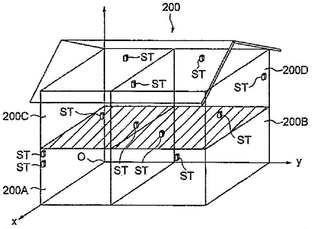
[0393] The power consumption pattern actually lived in the smart apartment is used as the predicted usage power pattern for making the power usage plan and the power request data for real-time mediation. Such as Figure 5 As shown, the smart apartment is an apartment for 1 or 2 people with a living room, a kitchen that doubles as a dining room, a bedroom, a toilet and a bathroom.

[0394] Moreover, in this smart apartment there are Figure 27 All of the 19 home appliances shown are equip...


PUM


Abstract

An object of the present invention is to provide an on-demand control system that supplies power to electric devices based on not predetermined priorities fixed to electric devices, but based on priorities changed according to the use status of the user. The on-demand control system can control supply of power of a commercial power source in real time in response to a power request necessary for the user and controls the supply of power according to the QoL necessary for the user through daily life. The on-demand power control system of the present invention is a multiple power source management system for an on-demand power control system, the on-demand power control system including: a plurality of power sources; a plurality of electric devices; smart taps connected to the electric devices; a multiple power source management apparatus that includes a memory and that controls supply of power to the electric devices; and a network for the multiple power source management apparatus connected through the smart taps, wherein the multiple power source management apparatus includes: power supply plan generation means for setting a power use plan of a commercial power source as initial values of a supply plan of a capacitor, searching a time zone with a maximum dissatisfaction among the time zones of the initial values to set the time zone as a time-shift destination, searching a time zone with a minimum dissatisfaction to set the time zone as a time-shift source, and repeating the process until the dissatisfaction of the time-shift destination is smaller than the dissatisfaction of the time-shift source to generate a power supply plan; supply power target value update means for setting a target value of supply power for each of the plurality of power sources and feeding back and updating an error between actual power supply amount and the supply power target value at each minimum control interval; and power and power source arbitration means for repeating a process of selecting a device with a minimum priority among an electric device that has requested power and electric devices in operation, selecting a power source with a maximum power source load factor, reducing or stopping power of the electric device, and reducing supply power of the power source by an amount of the reduced power until the following Expressions (1) and (2) are satisfied, thereby arbitrating the power and the power sources to satisfy Expressions (1) and (2) at the same time.

Description

technical field [0001] The present invention relates to a storage battery management system for an on-demand power control system in a home or office network, a program for multiple on-demand power management systems, and a computer-readable recording medium on which the program is recorded. According to the quality of life (Quality of Life) (hereinafter referred to as "QoL") required in daily life, the priority among electrical equipment is dynamically changed, so as to control the power consumption (Wh) without exceeding the upper limit value The supply of electric power includes an on-demand multiple power management system that introduces multiple power sources to a commercial power supply without restricting peak power, a program for the on-demand multiple power management system, and a computer-readable recording medium recording the program. Background technique [0002] The on-demand power control system is a system for realizing energy management in homes and office...

Claims


Application Information

Patent Timeline
Patent Type & Authority Applications(China)
IPC IPC(8): H02J3/32G06Q10/06G06Q50/06
CPCG06Q10/04G06Q10/06312G06Q50/06H02J3/32G06Q10/06H02J7/35H02J3/003H02J7/345H02J3/004Y02E40/70Y04S10/50Y04S20/12Y04S20/222Y04S20/242Y02B70/30Y02B70/3225Y02B90/20H02J3/14H02J13/00Y04S10/14H02J7/0063G05B15/02
Inventor 松山隆司加藤丈和田村健人
Owner NITTO DENKO CORP
Learn More